Turing Tumble Community

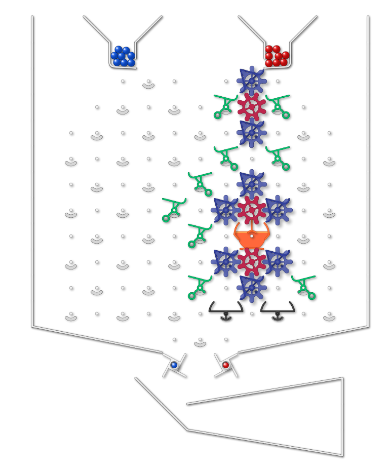
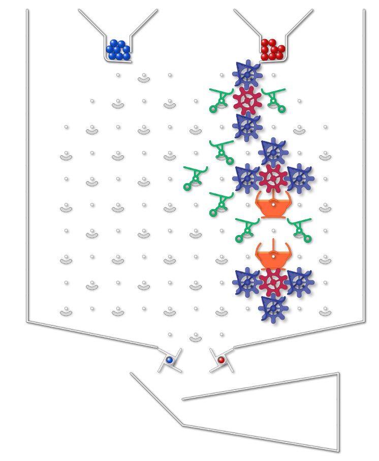
AND Gate (standard size simulator)

(So far I have only been able to do it on a standard sized simulator, because I needed more gear bits than supplied in a standard set).
Set up the board so that the position of a third (gear) bit © depends on the position of another two (gear) bits (A and B). You can manually set the gear bits before running.

When a ball has gone through, C should be the AND of A and B (if pointing to left is taken as “1” C should end as a 1 if and only if both A and B were initially 1 (regardless of what state C was in before). Running another ball with A and B unchanged should leave C in same position).

When a ball goes through, it must leave the position of the A and B bits unchanged.

Taking it further: I haven’t worked out if its possible yet, but would be pleased to see a NAND gate on a standard sized board (possibly with extra bits), and also an AND gate using only bits supplied in physical kit. And of course a NAND gate on a standard physical kit.
1 Like

I managed the NAND gate on standard sized simulator (but needed 10 gear bits). Feels like it should be possible to do it in fewer.

1 Like

Here’s what I have: (with True on right and False on left)

And gate

image

Nand gate

image

1 Like

Well done @Florentin. At some stage I will post my less efficient solution! Good to see AND and NAND can be done in a standard board. I tried to edit the challenge to take out the reference to being for a simulator, but seems editability has timed out.

1 Like

Which gear bits represent input A and input B?

There are three groups of gear bits (each set connected with a gear). Top set is A, middle set is B, bottom set is C. All the “logic” is in the gear bits and ramps. In this set up the ball is a bit like a clock pulse or trigger - it doesn’t have a boolean value, it just drives the process.
Note that in some situations people have set things up so that the balls themselves effectively represent 1s and 0s. (eg for inputing the binary string in to the Binary Modular Division).

Woah, I never thought of it that way. The gear bits and bits hold the boolean values, not the balls! It all makes sense now!

Hello,
Just got my TT a few days ago. Yesterday I managed an AND gate, similar to the ones posted here. While thinking about how it operates, it occurred to me that an OR gate could be made by flipping the entire AND gate around a vertical axis. IOW, it could be made by re-orienting the input and output bit convention: Left Gear Bit = ‘0’ becomes Right Gear Bit = ‘0’. So, I made a mirror image of my AND gate, and now have an OR gate. I thought it strange that they’re so closely related, but then I worked it out: (A OR B) = NOT ( NOT A AND NOT B).
image

1 Like

Impressive (and I like how you used Tumble Together to create this screenshot)

2024