Turing Tumble Community

Challenge #2: Long distance bit connections - how can we make them better?

This is something I’ve been trying to figure out for a while. Gear bits are a critical component of the marble computers. If you can’t send information across or back up the board, you greatly limit what the computer can do (it’s no longer Turing-complete).

The gear bits in Turing Tumble have some major limitations, though. You can’t really have more than about 4 or 5 gear bits in a row before they stop working correctly. Part of it is that there’s some backlash in the gears that increases the more gear bits you have in series. The other problem is that the balls aren’t heavy enough to overcome the friction of turning that many gear bits at once.

For the size of the board in Turing Tumble, those aren’t big problems, but if you had a much larger board, you’d have to build some extremely inefficient circuits to overcome the limitations. Half your board space and several balls would be required just to send one bit of information from the bottom to the top.

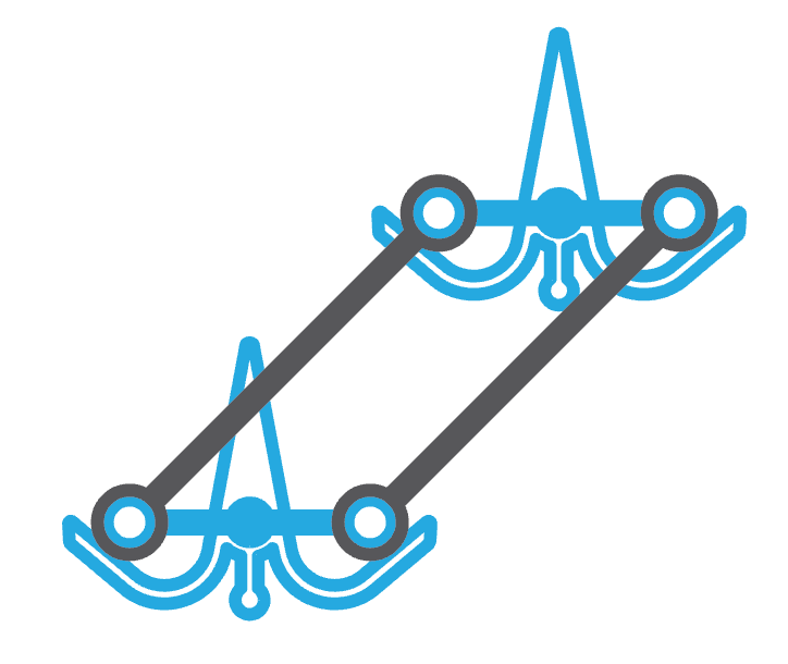
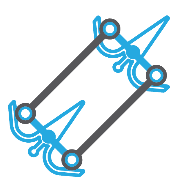
Can you think of a better way to connect bits together over long distances? The most obvious solution would be to make bits that are connected by thin strings. I’m sure it could work, but the hassle of tying little strings to bits would drive me crazy, and I’m sure the string would stretch out and get some slack in it over time, so you’d have to retie the string on a regular basis to keep the computer functioning.

Here’s the big challenge:

How could a long-distance bit connection be made in a way that’s a snap for people to add to the board and reliable?

And then the next challenge is:

How could it be made in such a way that one bit could be connected to not just one other, but several other bits without getting bogged down by friction?

I spend a lot of time in the shower thinking about these…

2 Likes

I would explore a snap-in cam LEGO technic-like extension solution on the front parts, so that it can either replicate one gear action to a further down placed gear, or, with a curved slider twist, short-cut the circuit to drive the ball directly further down.
But it’s only a hint, I’m not sure it would work, nor if I understood correctly the problem you try to address (I’m an image girl, a scheme would help for sure :slight_smile:)

1 Like

Super handwavy idea, but, rubber bands as belts?

Or like the lego technic idea above: lego technic chain

2 Likes

Yes, this might be a good way to create long-range connections. The connections could even be on the backside of the board so as to not interfere with what’s on the front.

You’re also right that what I wrote above isn’t very clear. :slight_smile: I’ll fix it soon.

1 Like

The Lego technic chain might work to allow long distance connections, too. One challenge with this approach is that each bit would probably need places for multiple chains to attach, because you might want to connect one bit to many others.

1 Like

What about a worm gear with threads and a gear on each end? I’m not sure the marbles would have the force to move several gears linked to the same worm gear, but it could be a way to reliably transfer energy back to the top.

2 Likes

That’s an interesting idea - long columns that transfer movement up to higher positions by their rotation. Here you are thinking a worm gear (probably one with very wide spacing between its teeth to reduce friction). I bet some other mechanism could be used to turn the column, too, if the worm gear doesn’t work.

I guess the downside is that it could only turn bits directly above it, but that’s not necessarily a killer. Good thinking!

Good outside the box thinking, but unfortunately that would not work. Worm gears can’t be “back driven”. Meaning the worm gear can drive the spur gear but not the other way around. If you try to turn the spur gear it will just be locked in place and nothing will move.

if I understand the issue correctly, it sounds like you’re trying to find a way to transmit motion from one gear to another, N pegs away. I assume You want to transmit the same direction of motion, and not the opposite direction?

I think the idea of keeping everything on the front of the board would be important. If the idea of this game is to make computing transparent, then putting stuff on the back means out-of-sight, out-of-mind, unless the base game board itself is transparent.

what you could add to the top of the gear is a connector shaped sort of like an upside down football goalpost. The fork part would be placed into two sockets on the gear, so that it doesn’t interfere with the gear’s movement on the board peg, but is restricted to move only when the gear does. the axle sticking out would be grooved so that any components attached to it would only move when the axle does, much like LEGO Technic axles work. You could then add a couple layers of your chain link to go in whatever direction desired to the destination gear. I’d also recommend some sort of alignment mechanism on the axle so that the chain link movement stays in the same Z axis plane.

Challenges to think about:

  • Finding some sort of connection loop (rubber band, chain link,etc.) that’s the right size without too much slack, or putting tension on the gears. Chain link is probably the best bet, but installing could be trickier than most kids will tolerate.
  • The further away from the board you get along the Z axis, the more the play between the pieces will amplify, I think. you could get to 3 layers out from the board with your chain link - and discover that all the dimensions are off and pieces don’t stay connected.
  • You might be able to mix and match transmission methods to give the optimal performance. Some scenarios might do better with chain link - others might do better with the cam-and-rod idea.

I can see you understand the problem! Yes, it needs to be able to transmit motion from one gear to another, N pegs away. It actually doesn’t matter which direction it turns the other gear (it could be the same or opposite). And I totally agree that ideally everything would be on the front of the board so you could see it.

A fork that connects bits at a distance could work. Different length connectors could be made available to span bits that are various distances apart. Besides the challenges you outlined, I see a couple more:

  1. A long connector between bits could easily be heavy enough to make it impossible for
    the weight of a ball to flip the bits.
  2. Friction will still limit the number of bits you can connect together at once.

I like the idea of mixing and matching different mechanisms to connect bits.

Thanks msmcguiver!

It’s hard to beat push/pull rods for simple and reliable long-distance energy transmission. That’s why Singer sewing machines switched from gears to rods very early on: the gears had backlash problems and didn’t last. And of course the TT uses a linkage for its longest information transfer: from the levers to the ball releases. Would it be possible to use something like that, except in front? The gear bits could have off-center pins which engage holes in a thin plastic strut. This may be similar to one of the technics solutions proposed above, because there is a part like I’m describing:

But I think for the TT it wouldn’t need to be nearly so thick and sturdy, and could probably even be stamped. Also I think the connection could be looser and easier to add/remove than what technics uses, because it doesn’t need to be stable in all directions; all you really need is to link the pin and strut along the strut’s axis and keep the strut from falling off. One problem is that the pin needs to be off-center in a direction somewhat perpendicular to the strut, so the linkage might only be possible in discrete directions. And you’d probably need to provide a number of lengths to avoid awkward overhangs, but these could be arranged as punch-outs on a single die-cut sheet so that would be cheap.

Also, supposing that you’re connecting bits in an up-down direction, placing pins to the left and right of the gear bit’s center would allow you to attach the strut on the same side or opposite sides of the two gears, which would allow for same-direction or opposite-direction bits. Of course to connect more than two bits with one strut, you’d probably need to attach on the same side, but if the struts are thin enough to stack on a pin and/or cross over each other, many complex arrangements are possible.

1 Like

How interesting! I didn’t know that about Singer sewing machines. It makes a lot of sense - gears are a pain, what with the backlash and the friction. Rods are indeed the technology of tomorrow.

The biggest problem with rods in TT is that they need a counterweight to balance out their weight. And the counterweight would have to be different for each length and angle connection. It’s certainly possible, but how do you do it cleanly, without requiring the person programming the board to carefully balance each and every connection?

Ah, balance! Funnily enough I woke up this morning wondering whether a rack and pinion mechanism would do the trick (kind of a rigid version of the chain solutions mentioned above), and the problem of keeping the rack engaged with the gears suggests a solution to the balance problem as well. Let’s see if I can convey the concept with ASCII art:

     __________________
    (O________________O)
    // |/ |/ |/ |/   //
   //               //
  //_______________//
 (O________________O)
    |/ |/ |/ |/ |/

So what you have is two racks with teeth on the back side, connected by a linkage that keeps them parallel. Putting the teeth on the back side allows the mechanism to just sit on the gears, using the tilt of the board to keep it in place. This should be self-balancing if placed horizontally or vertically. I’d have to think more about the diagonal case but intuition says it should be balanced as well.

One potential issue is that the distance between the two racks will change somewhat as the gears turn, and the teeth need to stay engaged while that happens. It’s possible that the geometry works out okay, since the gears are only turning about a quarter turn and some slop is acceptable. But if not, it might be possible to mold the connecting struts with living springs, so that their middle section is zigzagged and therefore slightly stretchy so as to pull the racks toward each other a bit. If that doesn’t work, the connectors could be rigidly fixed perpendicular to one rack and sliding in slots on the other, which would keep them parallel and at a fixed distance. In that case the two connectors should have their rigid attachments on opposite racks so as to maintain balance.

A neat feature of this mechanism is that once it’s placed onto the first two gear-bits (or gears), you should be able to put more gears and gear-bits on either side of either rack, making a number of interesting geometries possible, including mutually-inverted gear-bits.

1 Like

Let me add something to the wish-list. It would be nice to be able to connect two (non-adjacent) gear bits in a way so that the connecting mechanism is off the board enough so that under it one can still have ramps or other components. Right now if you want to connect two gear bits several columns apart, the line of connecting gears and gearbits cannot be crossed by a ball without going through the mechanism. This would seem to present a significant limitation-of-planarity on the ability for information to flow on the board.

1 Like

@lennypitt: Yes, I’d like that, too. I thought I’d point out, though, that it’s possible even now to cross a ball through a line of gear bits without changing their positions. In the example below, there’s a line of gear bits going from top to bottom.
image
How can we get a red ball to go through them to the left side of the board without changing the position of the gear bits? Like this:
image
We add one more gear bit off to the side that returns the gear bits back to their original position, regardless of the position they were in to start. In this way, we get the red ball to the left side of the board and the gear bits are unaffected.

You might have already thought of that, but I thought I’d just point out that while it would be convenient to have another dimension for this kind of thing, it’s not necessary.

ASCII art? That, sir, is just the best. You brought the forum to a whole new level.

This could be a good solution, and I especially like the ability to invert the connection between the bits. I ran into a couple problems with it, though. Here’s what I was thinking of:
image

I 3D printed something like this, but quickly realized that I screwed up. Because, while this works spendidly:
image

This doesn’t flip:
image

So then I tried to raise up the connection points so that it would flip, even in the above situation:

image

And that worked, except that there was too much weight on top. So if you connected a few bits together like this, the weight quickly became too much for the little balls and they couldn’t flip the bits anymore.

If you could overcome the weight issue - somehow offsetting the added weight of the connectors, I think you could get it to work. I just couldn’t think of a good way to do it.

Yeah interference is definitely an issue with the rods and pins, which was why I was only thinking to put them on one side, but I hadn’t been thinking about balance. Here’s a rough but hopefully clearer drawing of what I’m getting at with the rack and pinion drive:

gearbit-rack

Being out of practice with my CAD skills, I’ve used transparency to show the 3D nature of it; I hope that comes across okay. The rack effectively has two layers, the front part being the main structure and allowing it to rest on the gearbits, and the back part being the teeth that engage with the gears. One advantage of this type of design is that it could be made fully compatible with the existing parts.

1 Like

BTW, it might be a good idea to have the gear unit have an adjustable lever to make the gear stick out more. That way, you can build two separate gear chains next to each other.

I have done some experiments.

Thread actually works quite well. However, as Paul said, it is quite fiddly to connect. You need to thread it onto the cogs in such a way that it doesn’t come loose when they turn. However, you don’t need to tie a knot, just wrapping the ends around the cog a few times is enough to keep it in place. My first instinct was to connect them tightly, but I found that you must have it a little bit loose or the cogs won’t turn fully one way and the ball will get stuck. Video:


(The red cog is for weight to make sure it doesn’t bounce back to middle position as the ball leaves.)

Next I tried to construct push/pull rods from what I had to hand. My best effort involved threading cable ties through two gear bits to create poles sticking up on one side, which I then connected with a strip of thin card (cut from a flier) with a hole at each end. Keeping friction low was a challenge, though that would be easier if the pieces were plastic. However, I think the bigger problem was weight. The strip of card was very light but was still significant. I was able to counterbalance it by having the other end of the cable tie stick out the other side a long way. However, the I think the total additional weight on the cogs created more friction with the board. I never got it to work reliably. If someone wants to try a 3D printed plastic solution, the rod will need to be very thin and light, and some counterbalance weights included.

Finally I tried an elastic band. The one I had handy turned out to be an awkward length for vertical connections. Diagonal connections were unworkable as you always need a piece below the top gear bit, and that always got in the way of the elastic band. However, I did get it working sideways:


You will notice that it is quite loose. I found that this the only way it works (as with thread, if it’s too tight the ball will get stuck). Each cog tends to slightly favour one side or the other - as the band is loose the ball can exit each side; however, entry is only reliable coming from one side.

The band can slip to the back at the top of the cog, where it physically blocks the ball. The central blue bit in the video helps prevent this.

If anyone wants to try making new bits, I suggest trying a circle of plastic around the gear bits/cogs and above the teeth to enable elastic bands to sit on them reliably and a bit higher. Add a set of elastic bands of various lengths and that should work nicely.

2 Likes