Turing Tumble Community

Create a counter that can be incremented and decremented

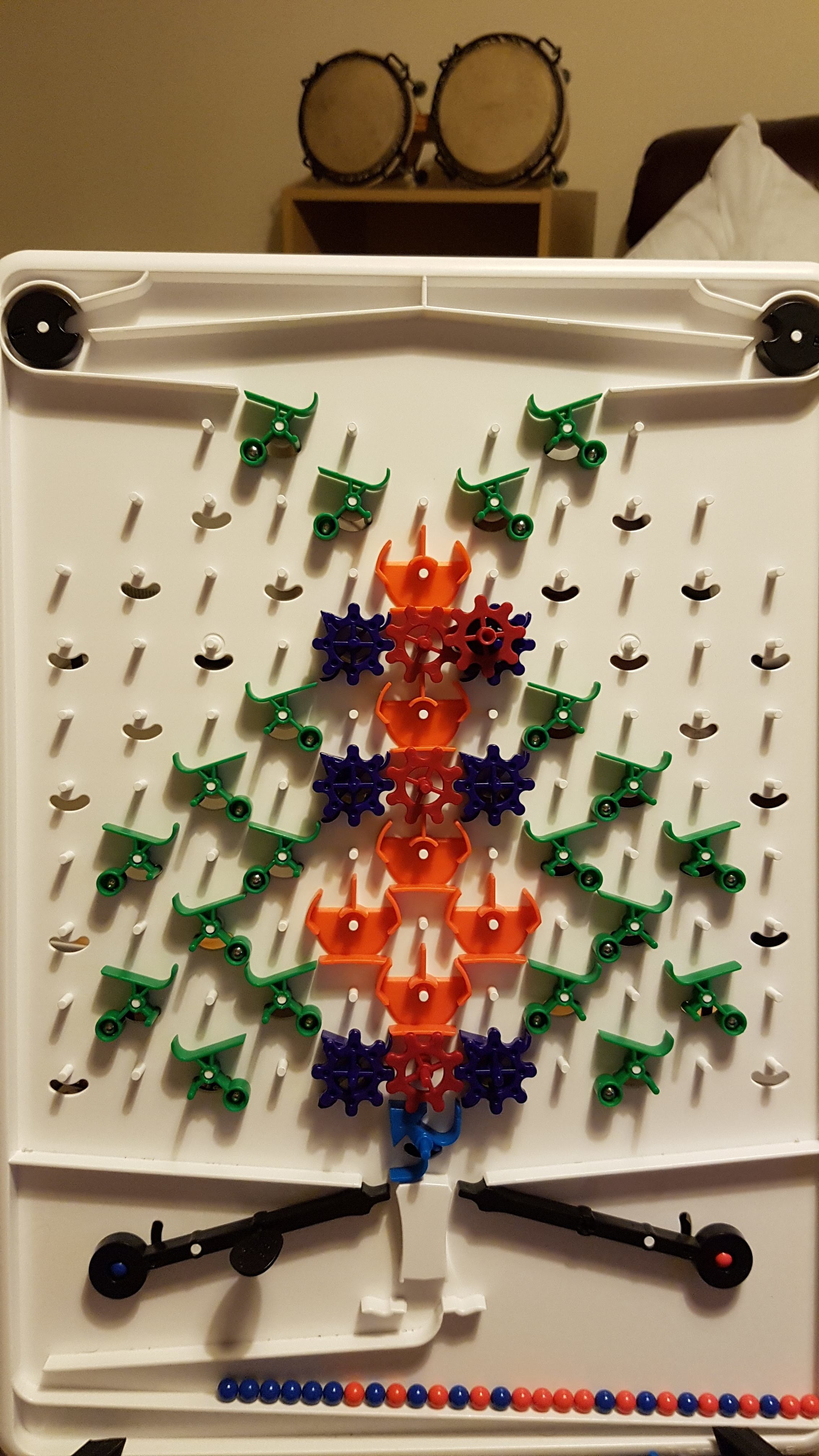
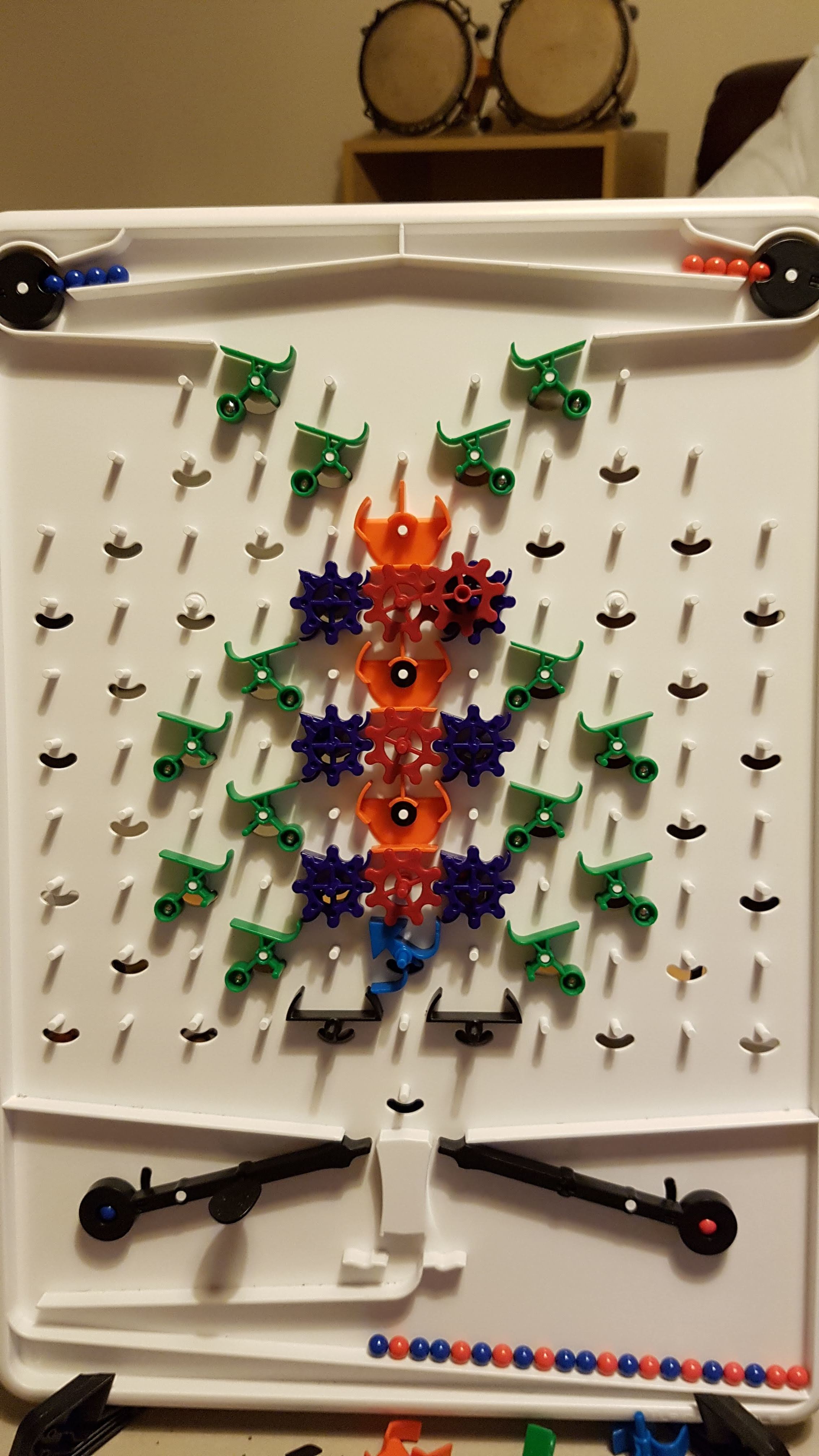
Create a counter structure that can be incremented by releasing a blue marble, or decremented by releasing a red marble. Assume you’ve got enough parts of any type, and enough board space. Assume no overflows in either direction. For example, suppose the counter can represent up to the value 7. Then, assume that at all times 0 <= #blue-released minus #red-released <= 7, the counter should represent the #blues-released minus #reds released.

Note 1: I think this may be an important structure to prove Turing-completeness, following the strategy of creating a two-counter machine, which can simulate a TM assuming proper encoding of input and output. (https://en.wikipedia.org/wiki/Counter_machine#Two-counter_machines_are_Turing_equivalent_(with_a_caveat))

Note 2: I’ve got a solution, but am curious to see what others come up with.

Edit addendum:
Note 3: A more challenging version is to create an unbounded counter, assuming the board goes downward infinitely. Here, assume that a ball that falls to the bottom is intercepted.

Note 4: The original statement didn’t specify what should happen after the increment or decrement. It is fairly easy to just have balls intercepted. More interesting is to have them continue downward past your structure so they can be routed elsewhere and trigger more work as needed. The latter scenario is the basis for the solution to Note 3.

5 Likes

This one was trickier than I expected. Emulator link

The repeating unit consists of the first four full rows, starting with the gears and gear bits. For the first unit, not all pieces are needed; they were included for completeness. Also, I have crossovers, but they’re not strictly necessary. In fact, any redirecting piece (not a gear or intercepter) will do the trick since, in this setup, the central columns just serve to carry the balls to the bottom of the board.

Here, the central column of gear bits is the counter. Technically, this column can be omitted as all three columns of gear bits are linked and the only reason the left and right columns are needed is to separate the incrementing and decrementing paths.

1 Like

That is basically the same idea I had, but seems to be a bit wider than necessary. Here is my somewhat simpler solution. [Side question: how did you get the emulator to use a larger board?]

For a finite number of these units, it seems easy enough to test if the counter is at 0. (Try to subtract, and check for underflow by the ball coming off the bottom right.) For an infinite number, testing for 0 seems impossible to me at the moment, at least with these designs.

If we don’t care about the ball passing through, then it can be done much more easily.

2 Likes

Ah, I see, you pass the ball through in the middle to avoid interference at the ends. Clever.

You can pass additional parameters in the URL to change the width and height, as I discovered when I looked at the JS code. Specifically, my link has &w=19&h=19 at the end for a width and height of 19 units. For both dimensions, 11 is the minimum and 27 is the maximum. Additionally, the width must be 4x + 3 for some integer x.

1 Like

Aha… Thanks. (I suppose I should have just looked at your URL).

1 Like

With the ball passing through there’s an even simpler solution: Solution with pass through

It’s the same idea, but with the addition and subtraction sides swapped, as this simplifies the pass through.

2 Likes

That’s brilliant and quite elegant!

1 Like

That’s beautiful! Never would have thought of doing that.

Wow, that should have been a puzzle. A really hard puzzle. Nice work!!

1 Like

If we had the reflector piece, couldn’t we reduce the layout to something even simpler, with just two columns of gear bits. The left and right columns would contain the gear bits, and the middle column would alternate between gear (connecting the left and right gear bits), and reflector, as shown below.
counter-with-reflectors

3 Likes

And if this solution is correct (I haven’t built it myself), I believe it also gains the distinction of being the first practical application of the Reflector! Nice work!

Yeah, I jumped straight to Eriban’s solution and the thought that having blue to subtract and red to add would be simpler (letting you fit an extra bit into the counter)

Nice puzzle. Here are two solutions using parts in the box, one using pieces as they were designed to be used, and one using reflectors (crossover + some washers = reflector), which is more compact.
20180830_010348
20180830_012406
I use a normal blue bit at the bottom to make the register 4 bits.

Given a taller board, both designs could easily be extended to more bits.

2 Likes

It’s been 5 years, no idea if anyone will see this. Anyway what do you think of this one? Left = overflow, middle = success, right = underflow, I believe this can continue forever in a bigger board
Simulator link

This is nice - thanks for sharing.

1 Like