A typical workflow with a computer is:
1\ user inputs something
2\ the computer does something (invisible)
3\ it spits out an answer (visible)
These can of course take many forms
1\ user input: Type a number on a calculator or
Type text on your keyboard
2\ does something: adds two values together or
searches the internet
3\ output: Displays a number on the screen
Displays a hit list
This 1,2,3 workflow is what we are used to in the real world.
TT concentrates on (2) and does a good job of making the invisible visible.
What is missing for a real-world connection are steps (1) and (3).
Below a probably very poor attempt to connect TT with the real world…
TT is obviously very limited in processing power. Which is OK, that’s not the aim of TT.
But it could be potentially used at least to demonstrate a very simple 1,2,3.
Going back to the definition
1\ user inputs something
manually set 3 bits to create a number (0 to 7)
2\ the computer does something (invisible)
convert the 3-bit number to a corresponding 8-bit Byte
3\ spit out an answer (visible)
Displays the 8-bit Byte on a 7-sergent display
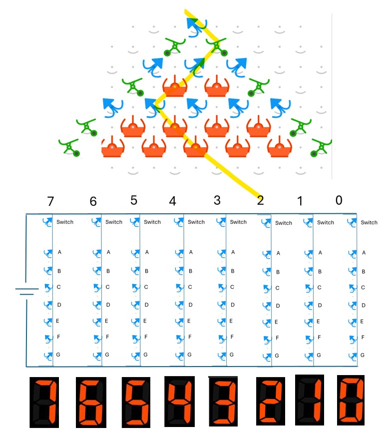
Step 1\ manually set 3 bits to create a number (0 to 7)
Examples 000 = 0, 001 = 1, 010 = 2 etc.
Example shown below is 010 = 2
First row is the Bit 1, second row is bit 2 etc.
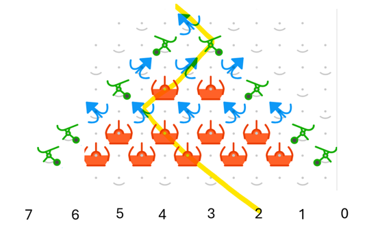
Note all bits in a given row must be pointing in the same direction.
This could be achieved by mechanically coupling using already available TT components.
Step 2\ Converts the 3-bit number to a corresponding 8-bit Byte
A single ball (think of as an electron) falling through the chain will get sorted according to the number dialed in by the user. eg. 010 will go to position 2.
Below is a 7-segement display labelled with the corresponding elements A-G
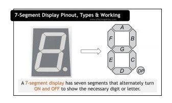
To generate a number 2 we need the following Byte
A ON
B ON
C OFF
D ON
E ON
F OFF
G ON
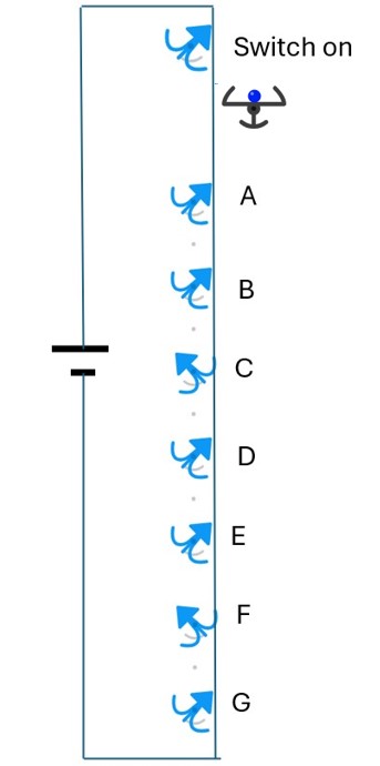
This can be represented as a column of bits. In this case hard coded ie. They do not move ie. non-programmable memory.
A 9th bit could be added above the column to turn the column on, like a row of xmas lights. An electrical connection between the 9th bit and each of the individual bits is sketched below.
3\ Displays the 8-bit Byte on a 7-sergent display
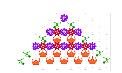
Extending the electrical connection to all 8 positions the rudimentary computer is now complete. A ball dropped from the top will be routed according to user input. It will then land in its corresponding position and display the result on the 7-segment display.
Of course, this relies on a mechanical to electrical conversion at the last step. Something difficult on practice on a TT board but easy to imagine at least, which is whole point. But a connection in principle be achieved using the pins of the bits protruding through on the rear side of the board. Then the 8 different Byte formations could be set up on an electronics breadboard with wire connections to the 8 different Bule Bits on the rear side of the TT board.
Breadboard, €10, Amazon
Then we have a rudimentary computer where the user can input a number in binary format by turning the 3-bits. It is then converted to an 8-bit format suitable for use on a 7-segment display. In other words a very rudimentary graphics converter.
The input in this case is somewhat archaic, having to physically turn bits to enter a value.
But pressing a keyboard is basically the above workflow in reverse. Here the user clicks on a familiar number, it sends a series of hard coded bits (a byte) which is the number in binary format to the PC for processing.