Turing Tumble Community

Turing Tumble Difference Engine

Here’s an approach for building Turing Tumble machines using read/write registers with a serial data bus. Each register stores a binary number and can support reading, writing, addition and other operations. Two parallel ball paths (0 and 1) are used as a serial bus for sending binary numbers between registers one bit at a time. Each register has 0 and 1 paths for both input and output. A simplified Babbage Difference Engine using some Digi-Comp II ideas is shown as an example.

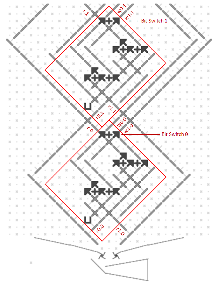
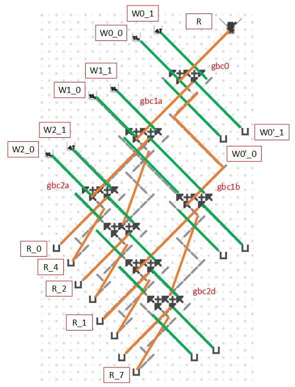
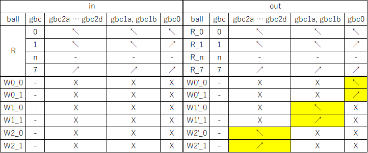
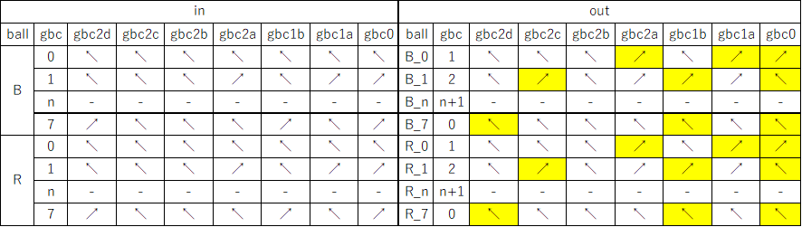
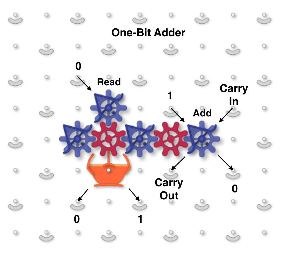
This image shows a one-bit read/write adder with gear bits set to a 0 value. Instead of using ramps for read-only registers and bit parts for write-only registers it combines the features of both using gear bits. An input 0 ball goes through two gear bits on the left and reads the current value to the output 0 or 1 path without changing it. A 1 ball toggles the rightmost gear bit to add to the value and handle carry in and out.

one_bit_adder

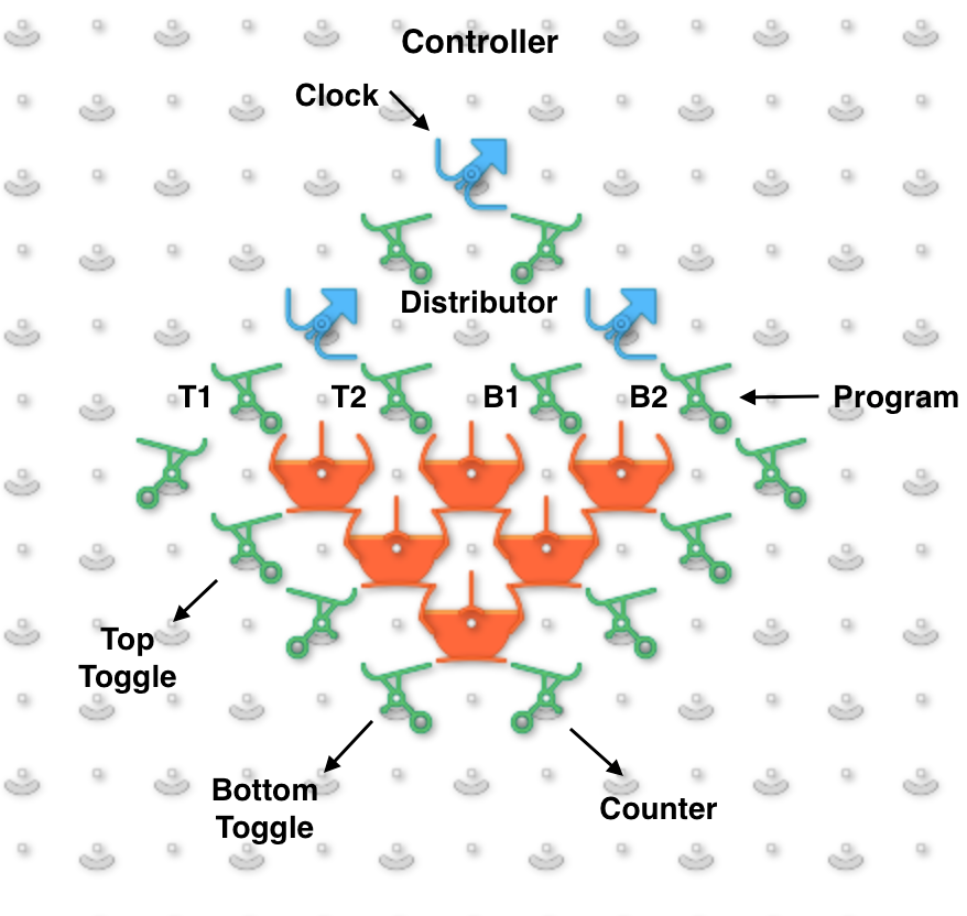
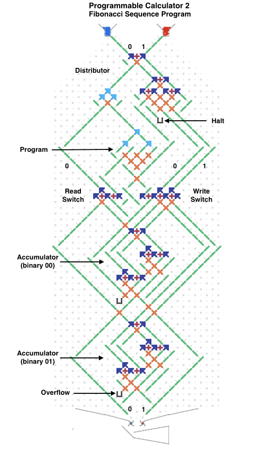
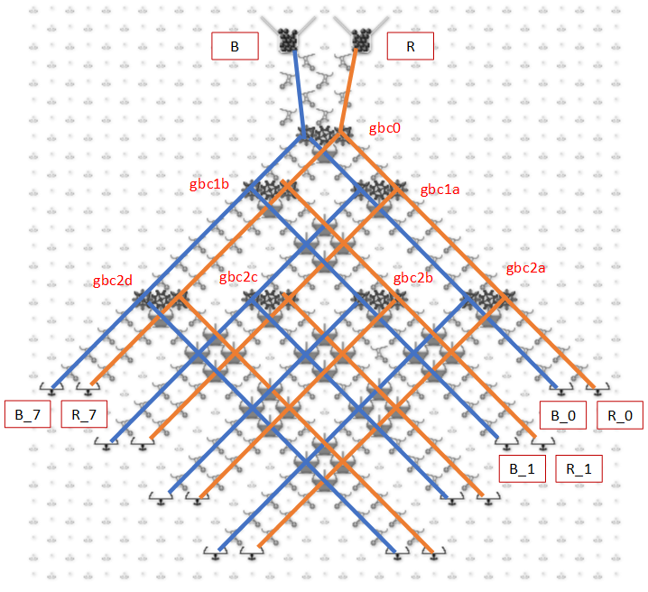
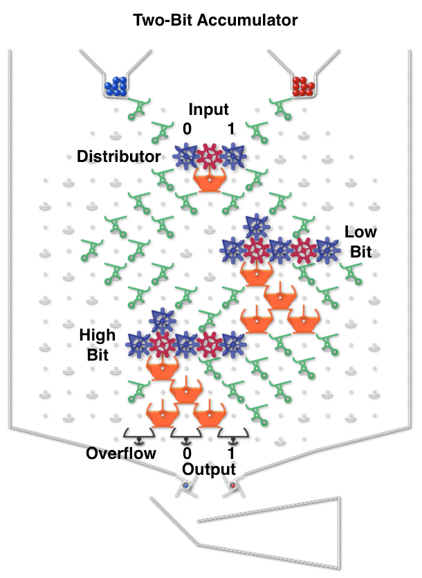
The next image and simulator link show a two-bit read/write “accumulator” register containing two adders. Each accumulator has a “distributor” that routes input balls to each adder bit sequentially. Binary two-bit numbers are sent serially as two balls with each ball in either the 0 (left) or 1 (right) path. An all-zero input number will read the current value to the serial output 0 and 1 paths without changing it. Any 1 balls add to the accumulator and handle carry and overflow.

To run, use the 0 (blue) and 1 (red) levers to input two-bit binary numbers and observe the arithmetic operations. For example, entering a red and then a blue ball for binary “10” will add decimal 2. The output balls in this example go to interceptors but could go to another accumulator. For example, a “00” number could be routed through two of these accumulators stacked vertically to read the first one and add its value to the second.

two_bit_accumulator

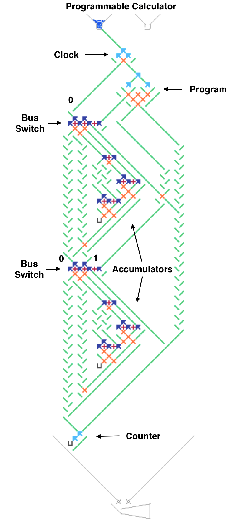
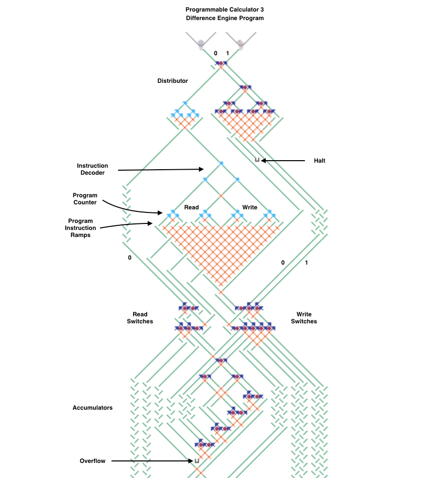
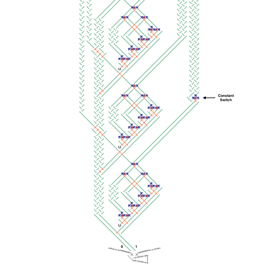
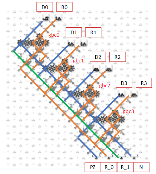
The next image and simulator link show a simplified Difference Engine using three four-bit read/write accumulators. It evaluates quadratic polynomials using only addition. Using more stacked accumulators will calculate higher order polynomials without using any more balls. The number of bits per accumulator can be increased. To match Babbage’s precision would require eight 64-bit accumulators.

The accumulator three low bits represent values from 0 to 7 (binary 000 to 111). The high bit clears every second number to all zeros to read the accumulator below it and add to the one below that. These clear bits must be initialized to alternating directions for each accumulator which alternates between adding even numbered accumulators to odd numbered ones and vice versa. Each even/odd loop iteration repeats two operations: add the D1 accumulator value to the f(x) one, then add D2 to D1.

difference_engine

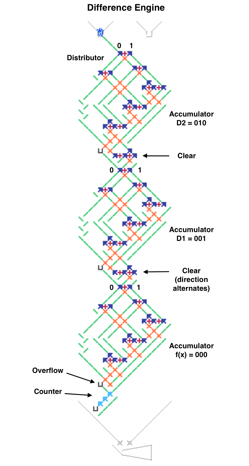
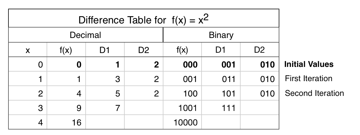
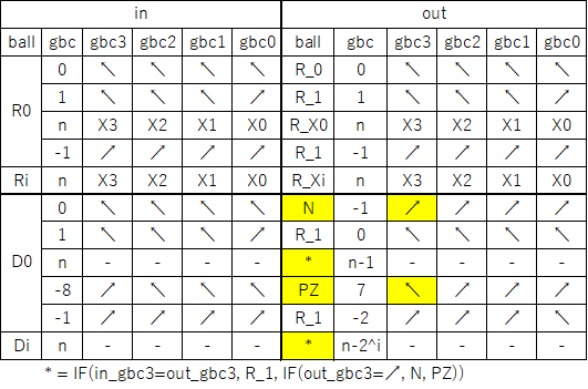
To calculate a polynomial function f(x) such as “x squared” make a difference table where each D1 and D2 entry is the difference of the two numbers to its left. Both decimal and binary values are shown in the table below for clarity. Enter the top row initial values 0, 1, 2 (binary 000, 001, 010) in the accumulators from bottom to top (already done for this example in the image and simulator link). Calculating initial values is more complicated for higher order polynomials using more accumulators.

To run, press the blue lever. Each full even/odd eight-ball iteration calculates the next row in the difference table with the f(x) results 0, 1, 4 (binary 000, 001, 100) in the f(x) accumulator until it overflows before reaching 9. The counter at the bottom pauses after each iteration to view the result (use the blue lever to continue).

difference_table

Roughly speaking, I think it works.

Here is the equation to write down

D2(x) = D2(x-1) = 2 ; for blue ball only
D1(x) = D1(x-1) + D2(x-1) = 2x + 1
f(x) = f(x-1) + d1(x-1) = n^2

“clear” seems to be a carry move, but I couldn’t figure out the details.

I think the serial data bus was used to multiply in textbook.
There it couldn’t be changed because it was using ramps, but here it can be changed because it is using gears.

I have an idea to add a “read/write” bit on top of the distributor, which will launch either a blue or red ball to the next “write”, depending on the result of the “read”.
This would make it possible to add memory from a lower position to a higher position, or copy memory, etc.

Thanks for the comments.

Typically each table column is calculated by hand in this order to get the top row initial values:

f(x) = x^2
D1(x) = f(x+1) - f(x)
D2(x) = D1(x+1) - D1(x)

Then the machine computes each following row by:

f(x) = f(x) + D1(x)
D1(x) = D1(x) + D2(x)

The “clear” flip-flops reroute all 1 balls to 0s for every other number so the all-zero numbers read and add alternating even/odd pairs of registers. This simplified the design since the machine only adds a register to the one below it.

That’s a good idea to route 0/1 as blue/red balls from the bottom to the top of the board to allow adding to a higher register, It should work but would be complicated. I’ll post another example where that idea might be more applicable.

1 Like

Here’s an example of a Turing Tumble machine that changes its register data paths while running. This image and simulator link show a programmable calculator that repeats a user-programmed sequence of instructions, similar to very early computers. A larger version of this machine could be programmed to simulate a Difference Engine.

programmable_calculator

The two bus switches on the left side route each two-bit read/write accumulator register on or off the serial data bus. The switches route both the 0 and 1 paths either left or right when toggled by a ball. The vertical bus on the left side bypasses each accumulator while the diagonal bus on the right goes through it.

bus_switch

The four adjustable program ramps define a two-instruction loop that controls the bus switches. The number of instructions in the loop could be increased by making the program controller bigger. The ramp T/B means Top or Bottom bus switch toggle and the 1/2 indicates the first or second instruction in the loop. If a program ramp sends the ball left then the accumulator is toggled on/off the bus.

The program repeats a multi-step calculation using accumulators as variables. Each instruction can switch any two accumulators at a time on the bus so the first one is added to the second one. This example only has two accumulators but could have more and some registers could do other arithmetic or logical operations.

The mathematical capability is limited since the accumulators can only be added to lower accumulators. As Yama-chan noted above, adding to higher accumulators might be done by wrapping 0/1 bits as blue/red balls off the bottom of the board back to the top.

program_controller

The “clock” at the top controls a four-ball cycle that sends two balls right to read program ramps and switch accumulators on or off the bus, then sends two 0 balls left to add one accumulator to another, similar to a CPU fetch-execute instruction cycle.

To run, press the blue lever to execute each instruction. The counter at the bottom pauses execution to view each result. The default program switches the accumulators on and off the serial bus and adds the top accumulator value 001 to the bottom one until it overflows.

1 Like

Here’s an improved programmable calculator that can add any accumulator register to any other, even a higher one, by wrapping a serial bus off the bottom of the board to the top as @Yama-chan suggested above. Programmable Read and Write bus switches select the source and destination accumulators for each instruction in a loop. A program is defined by the directions of the four Program ramps that control the Read/Write switches, the initial switch directions and the initial accumulator values. The number of instructions, accumulators and bits per accumulator can be increased by adding more parts. No long gear chains are used.

The Distributor 8-ball instruction cycle first routes a 0 ball left through the Read switch to read a bit from the selected accumulator to the bottom on either the 0 or 1 side. This causes the blue or red lever to release a corresponding 0 or 1 ball at the top that goes right through the Write switch and adds the bit to another accumulator. The next two balls read and add the other accumulator bit. Two more balls are routed through the Program ramps to allow toggling the Read and Write switches in a 16-ball 2-instruction loop. One unused ball goes to the bottom and the last ball ends each instruction at the Halt interceptor.

This image and simulator link show an example program that alternates adding the bottom accumulator to the top one and vice versa to calculate the first few Fibonacci numbers 0, 1, 1, 2, 3 before overflowing on 5. Release a blue ball to run each 8-ball instruction, then wait until it halts to view the accumulator results.

Calculator2

This is an innovative configuration where the length of the gear bit chain is realistic and the values are reusable.

I followed the sequence briefly.
Basically it appears to be an 8 ball cycle by the distributor.

1r: Acc0[0] is read
1w: Write to Acc1[0]
2r: Read Acc0[1]
2w: Write to Acc1[1]
3r: Invert Read-Sw. (Acc0→Acc1)
3w: NOP
4r: Invert Write-Sw. (Acc1→Acc0)
4w: Halt (NOP?)

note1

In the following diagram, for example, w1.0 means the path to write 1 to Acc0.
It is possible that Acc0=Acc0+Acc0, etc. can be calculated by devising a bitswitch.

note2

Even as it is now, the Lucas number could be calculated by changing the initial conditions.

It can be extended by increasing the size of the distributor.
I agree that this would easily increase the number of bits.

I also believe that the program can be increased so that Pell number can be computed.

On the other hand, care should be taken to increase the accumulator.
This is because I think the configuration of read switch, etc. to become more complex.
In other words, the calculation of the Tribonacci number will be a issue.

Your explanation is correct. Expanding the program, distributors and accumulators is fairly easy but the read and write switches are more complex, as you said.

A larger version of this machine with 4 instructions, 4 accumulators and 4 bits per accumulator worked for the Lucas and Leonardo sequences and difference engine polynomials like cubic, triangular, tetrahedral and other numbers. Calculating Tribonacci numbers was not quite possible with this machine.

I’ll clean up the larger version and post it as an example of one way to expand this kind of calculator.

This machine extends the previous calculator design by doubling the number of instructions, accumulators and bits per accumulator. Below the old Read and Write switches are additional ones with twice the number of inputs and outputs to support 4 accumulators.

The top Distributor 16 ball instruction cycle uses 8 balls to read and add accumulator values, 4 balls to execute program instructions to control the switches, 3 balls are unused and the last ball ends each instruction at Halt.

The Instruction Decoder fetches and executes four 4-bit instructions in a loop. Each instruction has 2 bits to control the Read address switches and 2 for the Write switches. The unusual Program Counter runs a separate 4 instruction loop for each of the 4 switches. The Program instructions are defined by 16 ramps in a horizontal row. Only the balls that are programmed to go left will toggle a Read or Write switch.

This approach is simple but requires a fixed-length 4 instruction program. Programs with 1 or 2 instructions must be repeated to fill all 4 instructions. A 3 instruction program needs an extra no-op instruction that writes to an unused accumulator. The Constant Switch allows input serial 1s to be changed to 0s, making the bottom accumulator a read-only constant that can also be used as a no-op Write destination.

The example program in this split image is the “x squared” Difference Engine from above that generates 0, 1, 4, 9… in the third accumulator. This is coded as one instruction repeated 4 times with toggling effectively alternating two instructions, adding the second accumulator to the third one and the first to the second.

Calculator3a

Calculator3b

The Acc-switch created by @Phil naturally extends the Gear-Bit-Chain (GBC), when the number of Acc increases.
Therefore, the GBC becomes longer as the number of acc increases.
On the other hand, I gave top priority to shortening the GBC.

As a result, we were able to construct a means of accessing an arbitrary number of Acc’s in several 7-part GBCs, albeit on a fairly large scale.

A schematic diagram is shown below.
sw1

The operation is described in the table.
sw2

The path of the ball entering from read(r) is determined by each GBC.
Each GBC is set when the ball enters from write(w).
At this time, 2^n-1 GBC are needed to accommodate 2^n Acc branches.

I have also prepared a simulation.
https://jessecrossen.github.io/ttsim/#s=30,51&z=12&cc=24.5&cr=25&t=3&sp=1&sc=0&b=data:image/png;base64,iVBORw0KGgoAAAANSUhEUgAAAB4AAAA1CAYAAABWW1tXAAAAAXNSR0IArs4c6QAAArJJREFUWEfFWFGO0zAQfeOmBfEFBfG9d0D8V6seBc6BcpL2IKhHgO4N+NtdhYpvdr02aojT1vF4bCcL/YmqxHl+M+/NjEPWWov/8KN/AVzXNbbbLVarFTabTUtzAmACIAdttyNcX5+eKwS+BCMQbAScdgR7BjqKsQ/GgYdARwG3iz2mg/8Bpk7HhaE+2YAD55hOBhxijpqAL3HBjWbsGLRYINSwp2sEexJgF25H1F1j4c4Ajvu1z3WHKlosXrny/Opy65jGwEXGkmV6lTrreMJi/Z1SqyXwnmEHLj2fVUAkv0pgg/spjPtw+jVZCGtsM2KO/VYt+VVkToTjCJAFnOrXAXgHdk4iADyNXxN9/Dx+TfKxlJtivzJDwkWoJfASv7aeTZlAJvcrMwwEVT3ITaFfi7rTWL9Kw0CUsdRffUbSZgUf/70t9VcflCsu3CElXrlcU/e6DjuyOuskDAMscP9yf3CTBjlmsz7zcI4dw+6amjtus6EKNgDmikSq0LixJ9qPxUVM7sR1XZzPwXvG5LWugYAShSaW3Vg/HliFGeS4IlHUjznmbjPZQmOMHPXxWKHFvnCIPmZzJghN+qwS9vFEQitiPJg4nCUyhVZUq6cSWgg8ebwtFVoRYz/cuUIbl+NCoRWpmg2PN7jldKOkthgUA8M8tUEUA1/MS16/5k6TSScJKSeS0FjwwIGtnemyzseS0FyRYcCSpkwpAtKXO3F9DuM+nAmMngVYemnKfQKs/XT1ATfvNQxVWJDFo6kApWDvDA7rBsubN9CYY1EpqN/Ag33ETAEHdcC6WWL/TsPSKyyeNExlQHYO2xjcH9ful9BGYUbAy5mCfiJUdI8W+OPVZzTL73irDfCCUGkLPa+gHjSa+a/+5bALVFbB4PjcDObW4Oe6weuvS+DHN+xTqHbP/AEQ7WMidEhMCwAAAABJRU5ErkJggg==

There is only one path that can be switched in this configuration.
When calculating Acc, there is a possibility of 0 and 1, so this configuration needs to be stacked twice.

Since any value can be written to the Acc-sw prepared this time, it is possible to access any Acc in any order.
In other words, using this, it is possible to construct a computing machine for squares, Fibonacci numbers, etc. similar to the example above.
Furthermore, by somewhat extending the previous components (Acc-switches, program counters, and accumulators), we can implement a computer called Subleq.

I’m now preparing a description and will eventually upload it.

I will now explain the second component, the counter, in a diagram and table.
If this unit is assembled in n steps, it can branch to 2^n routes in turn.
ctr1

Simulation is available at the following link.

https://jessecrossen.github.io/ttsim/#s=33,32&z=16&cc=19.5&cr=16&t=1&pt=3&sp=1&sc=0&b=data:image/png;base64,iVBORw0KGgoAAAANSUhEUgAAACEAAAAhCAYAAABX5MJvAAAAAXNSR0IArs4c6QAAAaVJREFUWEftlkFOwzAQRf8gRWzpDXqHXiAq52CByj2QT5JIXANyARY9Qtgj9iAhDWqI3dbJxDM2EgvIxqrrxM/z54+HmJnxyw/lQDjn0LYt6rpG0zSIf1vPlAXxvQkBOAax6wi73Rp931sZUAABUEfgLYfRvPv4QjYEgcBg+DEXYIhpTk74Df8j4SNxSx1ucI0HPKHhbbYi2XJ4KeAIuC/LjSyIOBdKk9QMIUkwBAQEBz4ExvSYICQJSqVRQ0gShJzwhSujfqggxHowJqUHCfXDCJKEkABSEliSdREiBRD+F06uBREhJBdY3aFxzSyE1QXW9bF/JxBWF0jusLjmDMLqguAKX7pHm8bzKdcEiFQSxndErgRzyTpAEBEO/a4fpX4hNDDRyVPzceMT7ye6o1SalASnybnojhBy3wtGmofQCvNakKk7fkialATJSEx8LHXVf+fuMEpjkcAsx9kLgjTay2qu5Upe5RoArQuknk8NIRW0SRILEi41nWoIU+dqXEwA8916g/3qE0QVcMngDwZVF6j4De8MbF6v8Liq8LJ/Nn5et/wLRRNsv1CtmRMAAAAASUVORK5CYII=

This counter has two inputs by using a gear bit.
This allows the ball to branch in sequence, whether it is red or blue, while keeping its respective route.
As shown in the table below, the internal state and the direction of the bits change in the same way whether the input is B or R.
ctr2

This unit is used to control the PC (program counter) and bits to execute the board’s operation in a predefined procedure.

The last unit is the Acc.
The “accumulator,” as the name implies, accumulates the values of balls that pass through it into bits.
In this implementation, negative arithmetic is used to support subtraction.
This means that the addition is flushed once to a spare accumulator and the sign is inverted.
For Phil’s implementation, the left and right are inverted.

In addition, the last stage, i.e., the most significant bit, is set as a separate output.
This is to allow the program to realize an “if” depending on whether the memory contents are positive or negative.

This route is passed only when the most significant bit of Acc changes in the DEC operation.
In the case of “read,” this route does not pass because it only returns the value of the specified bit.
In a DEC operation in which the most significant bit does not change, the result is not used, but is output from R1.

https://jessecrossen.github.io/ttsim/#s=30,27&z=16&cc=17.5&cr=13.5&t=3&sp=1&sc=0&b=data:image/png;base64,iVBORw0KGgoAAAANSUhEUgAAAB4AAAAcCAYAAAB2+A+pAAAAAXNSR0IArs4c6QAAASNJREFUSEvNlr0RwjAMhZ82oKEnI7CCj1HYg8teXBagYYPQ07CBuPjikPgnso1NSKPCiT8/PVkKMTNjg4f+Dtx1BKUYJq4lpWka9H2flDevYuoIrBgmJu0Y+bID/gV0ONsCbKAtAZfKJTeBNQyEFvyJM3iK5zHZ1mACgcEwEZbkGumfFNtQG1a60JbFZZSOsabnjmKjvLbny6q2vK7puXuPA4VW2nN/5xrhU3VX8Dw4JOwrVtrz1elkw0t6Lo7FUHP51nMRrBt6Bc+jwHN47D2X+nU02Kc85LkEdcZizAfmioV6e9Qe9jyWPgpOsYwBnpRqn9fOYaTTj+vJ4FLwLLCGE2H4JQ9FSXg2WNpYWt8ODDCfD0dc9y+cnruMeMfjJulz198ZR32/7MQLWwAAAABJRU5ErkJggg==

acc1

acc2

A simple calculator can be built with the three components so far (counter, switch, and accumulator).
From the top, arrange them in order PC-(Acc1r-SWr)/(Acc1w-SWw)-Acc2, with Acc1 containing a constant.
[1] Read the address of Acc2 to be read from Acc1r and copy it to SWr.
[2] Read the address of Acc2 to be written from Acc1w and copy it to SWw
[3] Reads the address of Acc2 specified in SWr and writes it to Acc2 specified in SWw.
The above three-step operation is performed.

Now, even when there are many Acc, the sum of all Acc, +1 to all Acc, etc. can be easily calculated.

The above is, so to speak, hardware coding, where the PC (program counter) cannot be changed arbitrarily.
In contrast, assigning an IP (instruction pointer) to one of the ACCs enables software coding with a high degree of freedom of control.

However, the number of steps increases because of the process from IP loading to execution.
Based on the above, “Subleq” is composed and shown in the followings.
sch1
sch2

Compared to the construction described above, there is no Acc1.
Actually, because the value can be moved from Acc2 to the SW GBC located at the top,
Acc1 is unnecessary.

There are three Ctrs (r/w, bit, and PC) in a row, so one cycle is made with 16 balls,
One instruction is executed in 16 cycles.
Details are shown below.
mat1

The above sequence is repeated in any cycle.
The read and write routes and codes for each cycle are as follows.
mat2

Subleq( a, b, c); Subtract and branch if less than or equal to zero, is consists of two operations.
I: [b] = [b] - [a]
II: if([b] <= 0) goto c

Read a in cycles 0,1 and b in cycles 2-4.
Read c in cycles 5-8 and convert to absolute address in cycles 9-11.
Calculate I in cycle 12 as [b]-=[a].
Cycle 13-14 controls “if”.
Cycle 15 performs the jump in II.

The “if” part is as follows
mat3

Following this logic, if-sw is rewritten in cycles 13 and 14,
“read” in cycle 15 is selected from “-1” or jmp.

The Subleq constructed this time is Turing complete.
With a limited length gear bit chain, an easy-to-program gravitational mechanical computer could be realized.