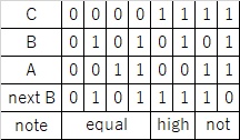
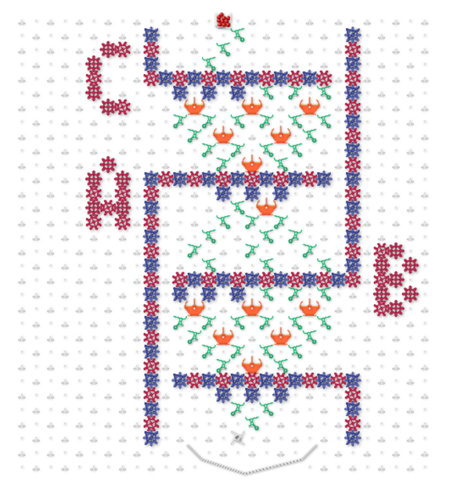
I made a Turing machine table.
[Simulation link]
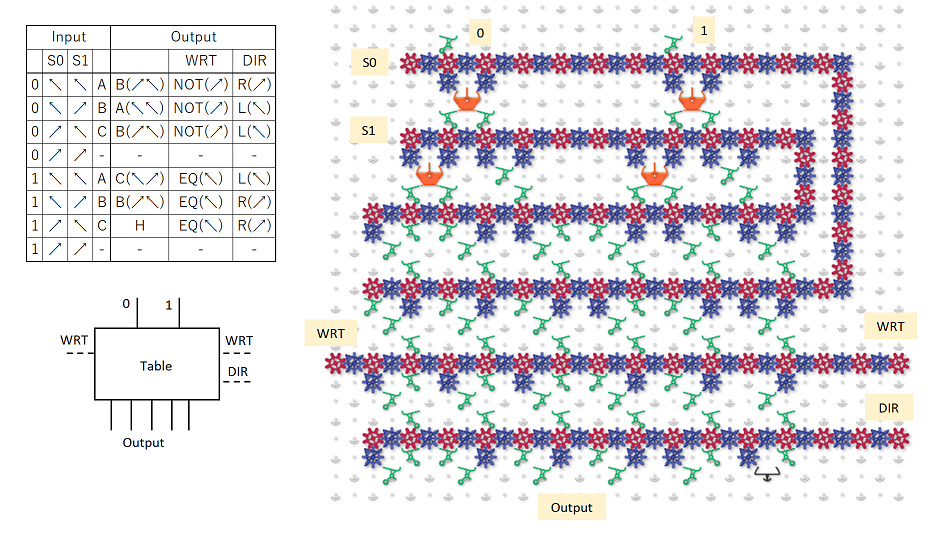
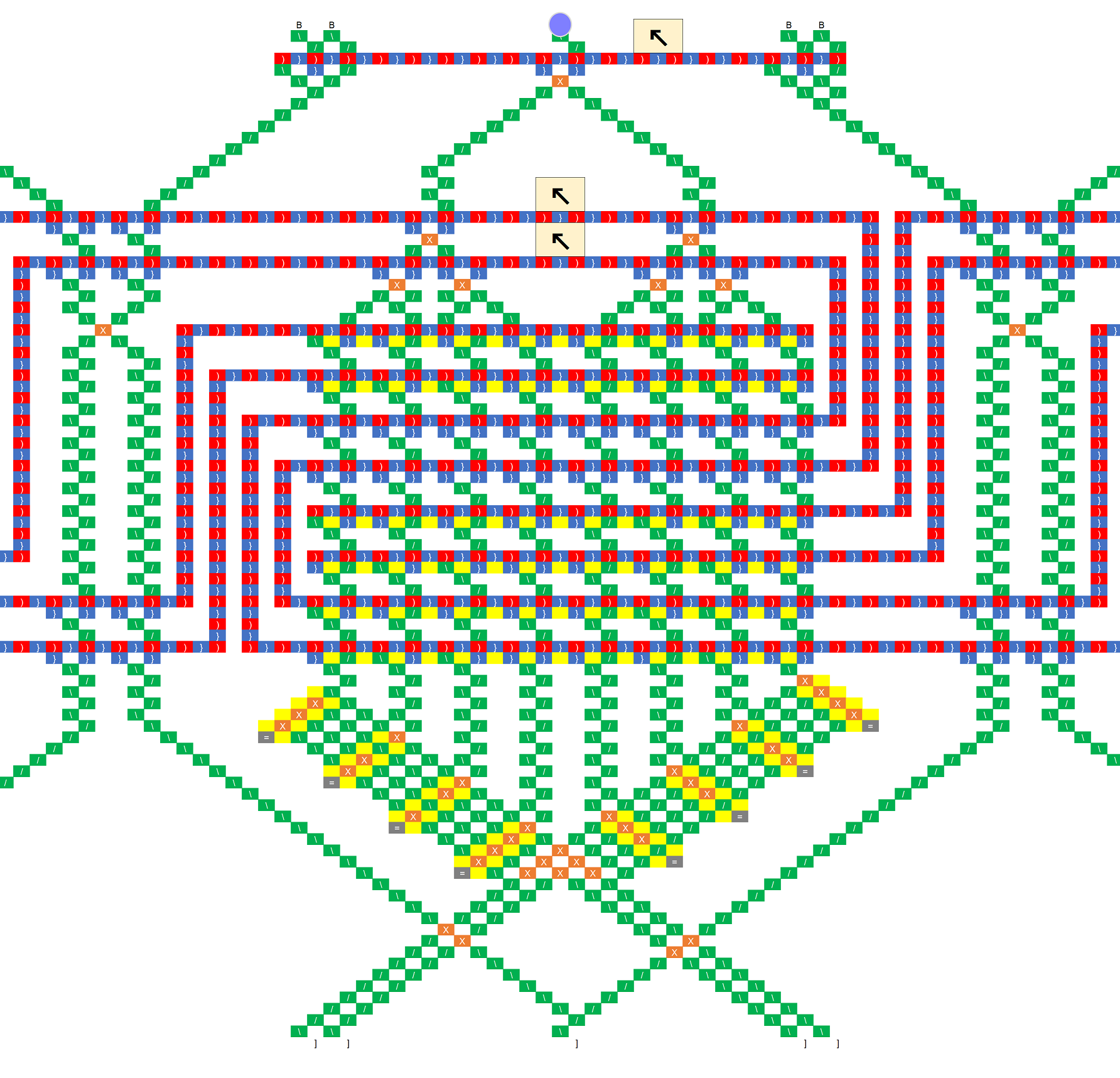
The inputs are 0 and 1, whitch value was read from the tape.
There are 4 sets of gear bit chains inside.
The top S0 and S1 are used to decode the head state of the Turing machine.
I decide like that,
A {S0 =  , S1 =
  }
}
B {S0 =  , S1 =
  }
}
C {S0 =  , S1 =
  } .
} .
The other two are connected to an external gear bit chain to rewrite the tape and specify the head movement direction.
Depending on the input and the state of the Turing head, the ball will branch to six ways.
Each sets the gear bits to predetermined.
By this, the ball can set each gear bit chain for any state.
The WRT line is extended to the left for convenience of control.
DIR represents the direction of tape travel. In this time, it is represented by one set because it always moves from side to side.
In general Turing machines, the head may not move, in which case two gear bit chains should be consisted.
The outputs may be indistinguishable, and the balls finally gather in one place.
But there is no space this time, so I did not make it.
=========
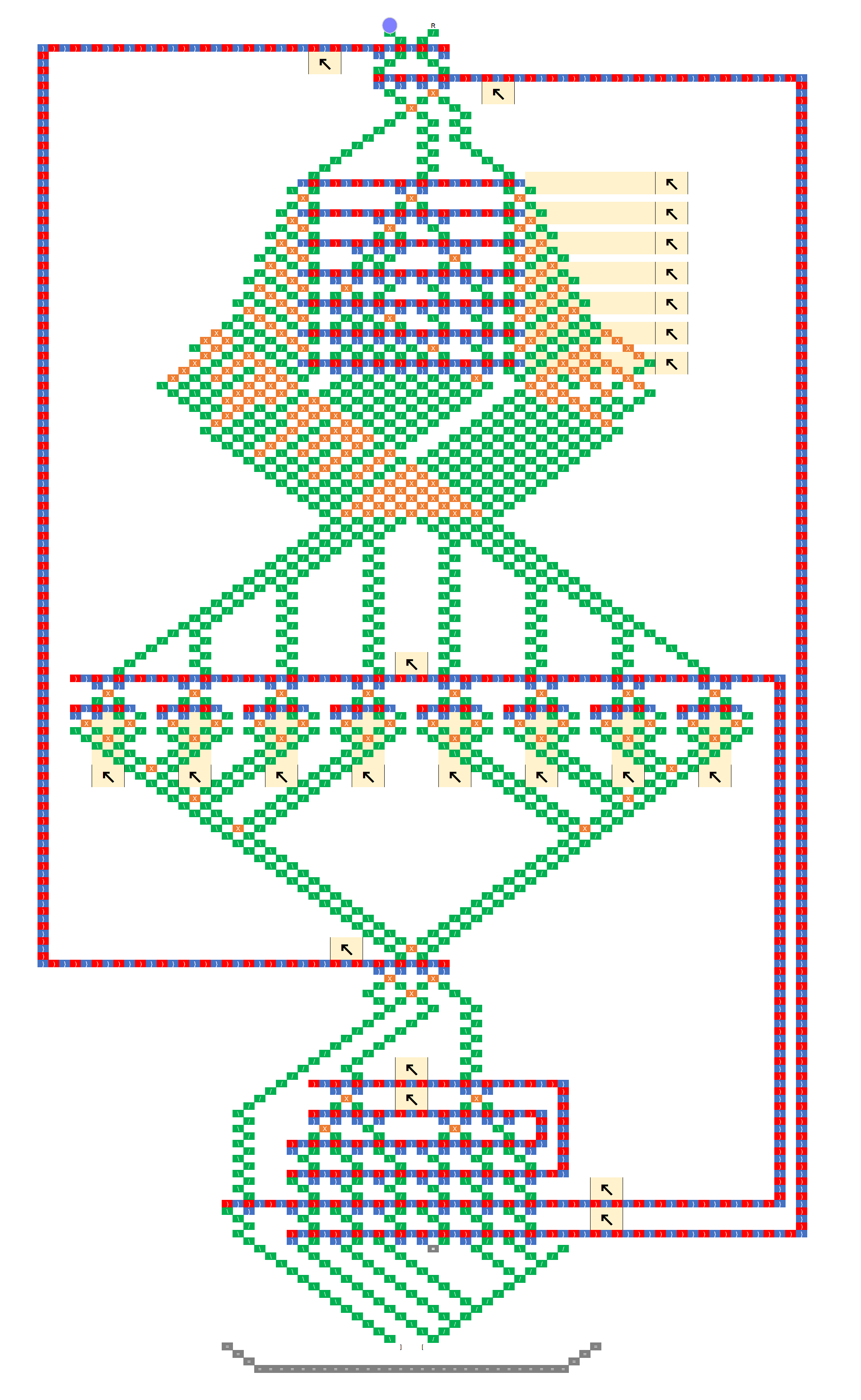
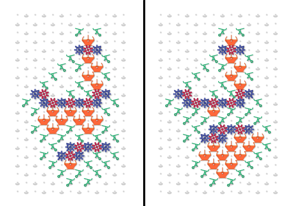
In addition, I summarized the entire configuration.
[Simulation link]
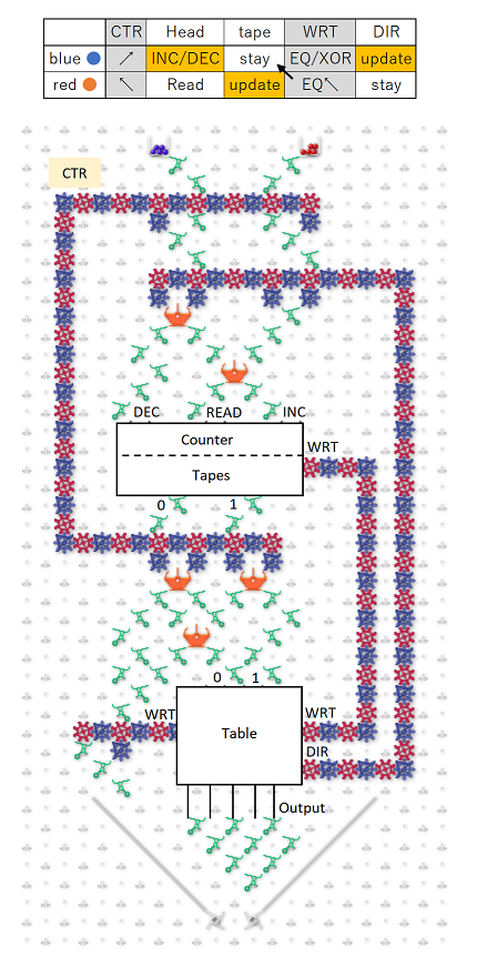
Basically, you can connect the counters, tapes, and tables from above.
However, if I take ball to that basic stracture,
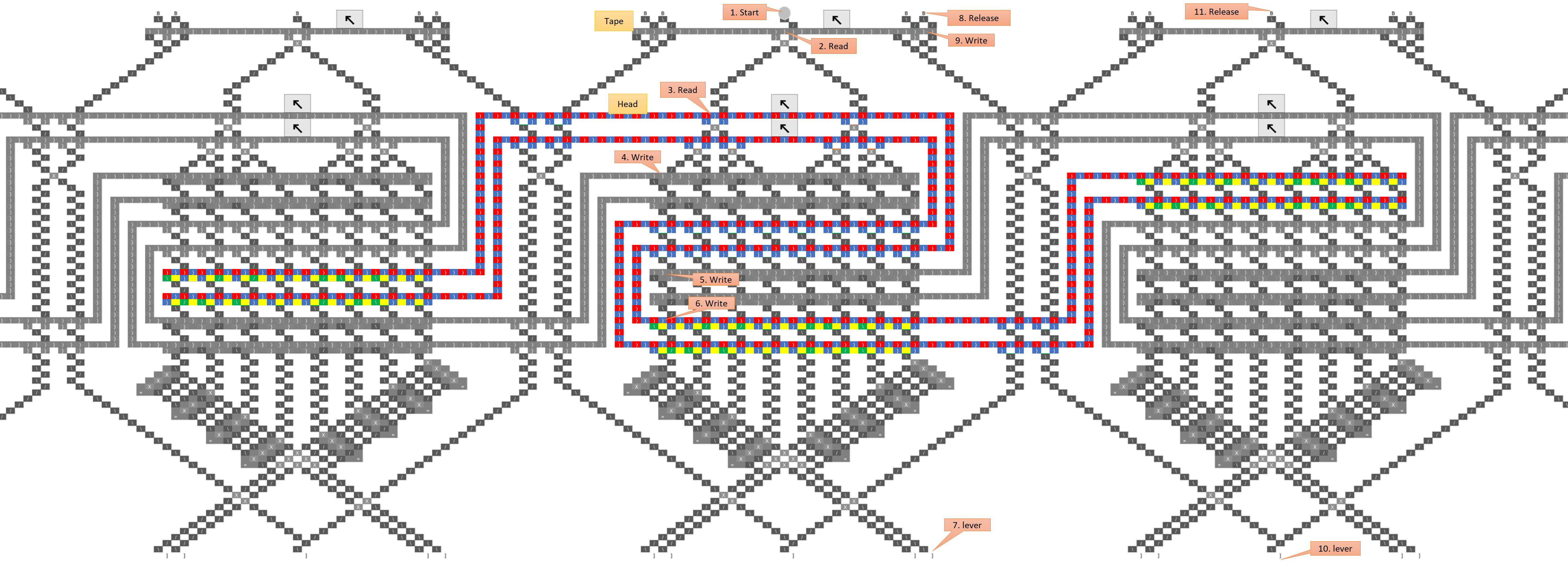
Read tape → refer table → (next ball) → tape moves → rewrite tape → read tape ,
Since tape moves before rewrite, I can not write to the correct location. so then,
Read tape → refer table → (red ball) → rewrite tape
→ (blue ball) → tape moves → tape stay* → read tape ,
We assemble the correct sequence using two balls like this.
CTR wire was introduced for motion control of red ball.
In order to stay tape which shown by*, the red ball makes the WRT line EQ.
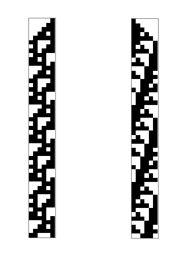
If this was actually connected, it should be a one-bit two-value, three-state, four-length Turing machine,
But it is may too large to realize.
