Turing Tumble Community

Some basic tips for building Turing Tumble to start things off

I wish I could shake your hand right now, just for clicking on this topic. I’m so excited to see the cool stuff you come up with! I have no doubt that you’re going to come up with new, clever ways to make the game or to modify it to do new things we never even considered.

I figure it might help to outline some of the things I learned to speed up the process and help you avoid some mistakes I made.
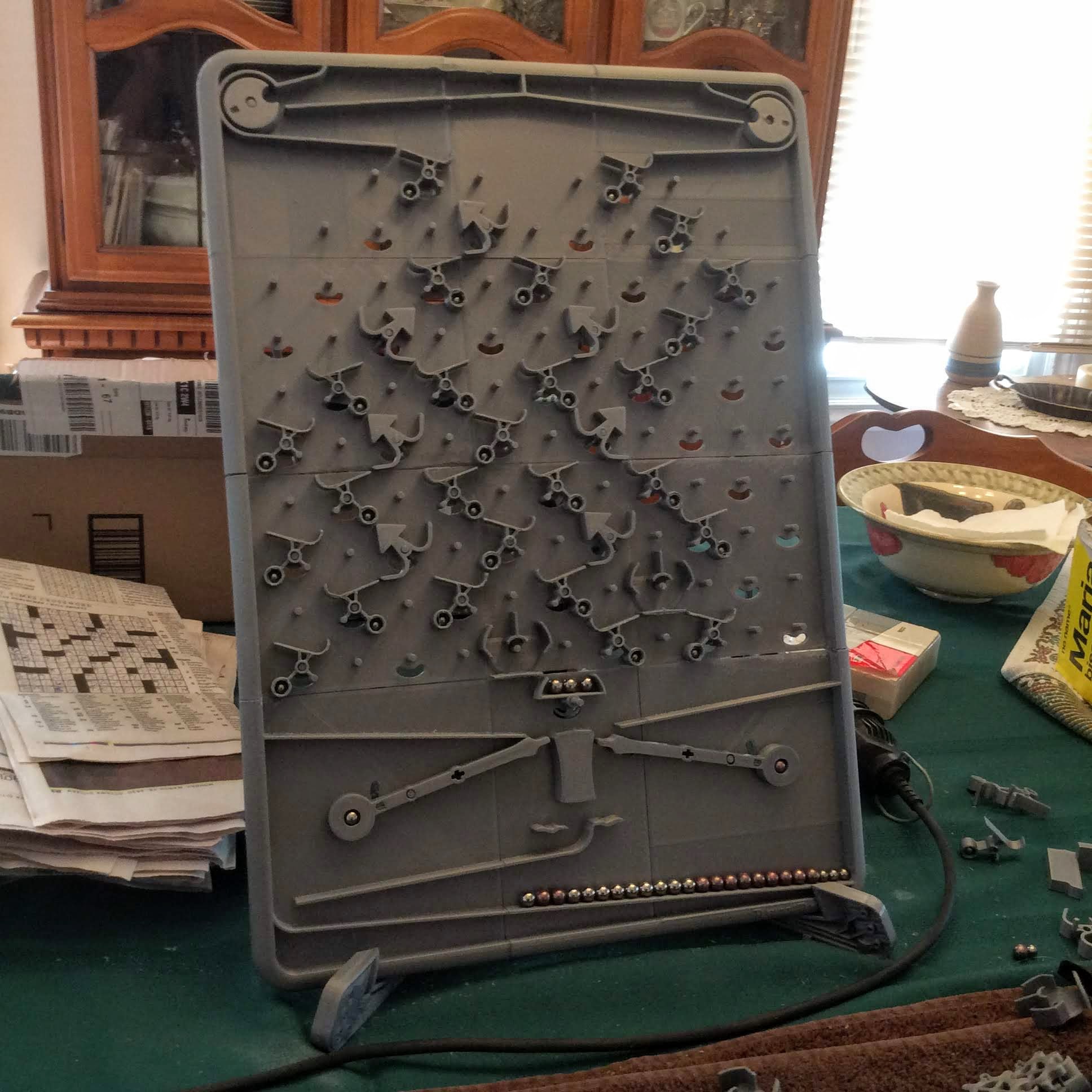
Making the Parts

It should be fairly straightforward to 3D print the smaller parts (the ramps, crossovers, interceptors, gears, gear bits, bits, the ball releasers and catchers, and the “standoffs”) with home 3D printers, as long as the resolution of the machine is good enough. (I’m not quite sure what “good enough” is, yet.) If you create 3D printing files of the parts with supports and it works really well for you, please post them here so others can use them, too!

Making the Game Board

3D Printing
The board is rather big. Too big for most home 3D printers. Still, if you want to 3D print it, you can send the STL file out and have it 3D printed somewhere else with larger equipment. There are a lot of companies that do this. You’ll find there’s a very wide range in price between these companies. One I found that had consistently low prices (a little over a year ago) was i.materialise.

Note that the method of 3D printing makes a big difference. I had the first big board made by SLS printing technology. The problem with SLS is that the board gets quite hot while it’s being printed. That causes the plastic to contract after it’s printed and you may find the board warps a lot.

Laser Cutting
With some ingenuity, you might still find a way to make the board by 3D printing, but I imagine for most people, it would be easier to make the big parts (the game board, the board supports, and the two connectors) by laser cutting them from a sheet of plastic or wood. Even if you don’t have access to a laser cutter, you could send a pattern out to a place like Ponoko that laser cuts the parts and ships them to you. It would require that first you create some two dimensional plans. In my second-to-last prototype, I used laser cutting to make the long connectors in the back and the acrylic board supports you see in the Kickstarter.

One challenge with this approach is in creating the pins that stick out of the board. Are there already some sort of little metal widgets that you could screw in to the board? Alternatively, could they be made of plastic rod, cut into little sections?

CNC Milling
This is the approach most likely to succeed, but also by far the most expensive. This is how I made my final prototype. The board alone cost about $800 to make. I used a company called IcoMold to do the CNC milling. Talk to me first before you do this and I can give you some drawings with critical dimensions to make sure they do it right the first time.

Other Ideas?
I’d love to hear some other ideas for making the board. We’re hoping to eventually make a massive version of the board just for fu- I mean for toy shows…yeah, for fun. 3D printing won’t work for that.

I’ll leave it at that for now. If there’s interest, I can post more details about my experience 3D printing the parts and the different part designs I tried.

2 Likes

Thanks Paul for the precious insights… Do you know when will we receive the links to the STL files? I can’t seem to find it…

1 Like

Shoot! I missed the Educator’s Pack backers. I just fixed it and you should get an email about it any moment now. I’ll send another email to you just in case.

I had a request to include the STP files in addition to the STL files. For some of you, STP files will be much easier to work with if you want to modify the parts.

I just put up a new version of the Virtual Pack (v1.1) that contains STP files. To download it, go to https://turingtumble.backerkit.com/backer/digital_rewards and you’ll see the new version there.

Currently the balls drop into columns 4 & 8. If one was going to make a larger board (say 21 columns), where should the balls drop? Maybe 6 or 7 & 15 or 16? Also how important is it for the last pin of the middle column be a Ramp type pin?

It seems to me that it would be more useful to release the balls closer to the centre so that you waste fewer rows if you have to merge or cross the blue and red paths before doing anything else.

I think if you were to make the board wider, you might add more levers and ball releasers. I haven’t thought this through, but you might even want some of the levers to connect to ball drops that aren’t directly above them. That way you could move the action to other parts of the board without having to transport a ball there.

How about a sensor to detect that the last ball is in the ball release? Maybe a lever that pops up when no balls are in the tray. Then attach that to a bit lower down the board. I think you would need a new bit piece (permanently placed near the bottom) that could be switched by the lever but not move when directing the ball left or right.

1 Like

Studs for backboard… basic(?) or FUN size … might be purchased here…https://is.gd/4hfJHE
IKEA part so readily available I guess, and there may be other sources Might need a washer at base to help ensure they are perpendicular to the board.

If I were going to make the board I would probably employ the same technique that I used for my Digi-Comp II Replica. I would split off the top part of the board with the pegs, channels, and holes keeping a pretty thin layer for the base, say 1 mm. I would further split that top layer into pieces small enough to fit on my 3D printer and print them. The Microsoft Build 3D application (which is free) does a great job of splitting STL files and it’s pretty easy to use.

I would then use the original board STL to create a DXF cutting file for the semi-circular and other holes. Use the DXF file to laser cut, mill, or route a base for the board from 1/4 inch plywood or acrylic (say) and glue the top layer pieces to it being careful to line up the holes.

Since I already own a Turing Tumble I’m not likely to try this but I’m pretty sure it would work.

1 Like

Could the board be made in sections that clip / glue together?

As for pins, would shelf support pins like these work? https://www.walmart.ca/en/ip/6mm-x-20mm-Furniture-Cabinet-Straight-Shelf-Supports-Pegs-Pins-10-Pcs-for-Home-Essential/PRD498CAHHR8R55

So I made this using my Ender3 few months ago. Wanted one for Christmas for grandson but all sold out so made it!
IMG_1919|499x499

It is not my finest work! My ender 3 prints detail very well but with a large piece like this there is a lot of room for error especially in piecing the board together. I spent much more time getting it to work mechanically than actually printing.

Here are some of my challenges:

  1. Seams: Glueing the board together left a lot of the seams slightly uneven and I spent a LOT of time sandng them down so the balls would flow properly. A dremel was goto tool.
  2. Gates: the pin holes were usually good enough to insert but invariably I had to ream them out with a drill bit to reduce friction.
  3. Slider holes: There didn’t seem to be enough give at each end to allow the gate to drop the ball so reamed out the ends of each slide a bit to give it a bit more swing room.
  4. Balls: got my ball bearings on line easily and tried the mustard vinagar bath to discolor w no effect. Finally I painted them w nail polish, a fine coat works ok.
  5. The length of the control bars had to be adjusted so the next ball would load correctly.

Anyway it was an exercise in mechanical engineering to get it running pretty smoothly. And just when my grandson was starting to play w it we got put in isolation :frowning_face:

I can’t seem to get to the BackerKit…