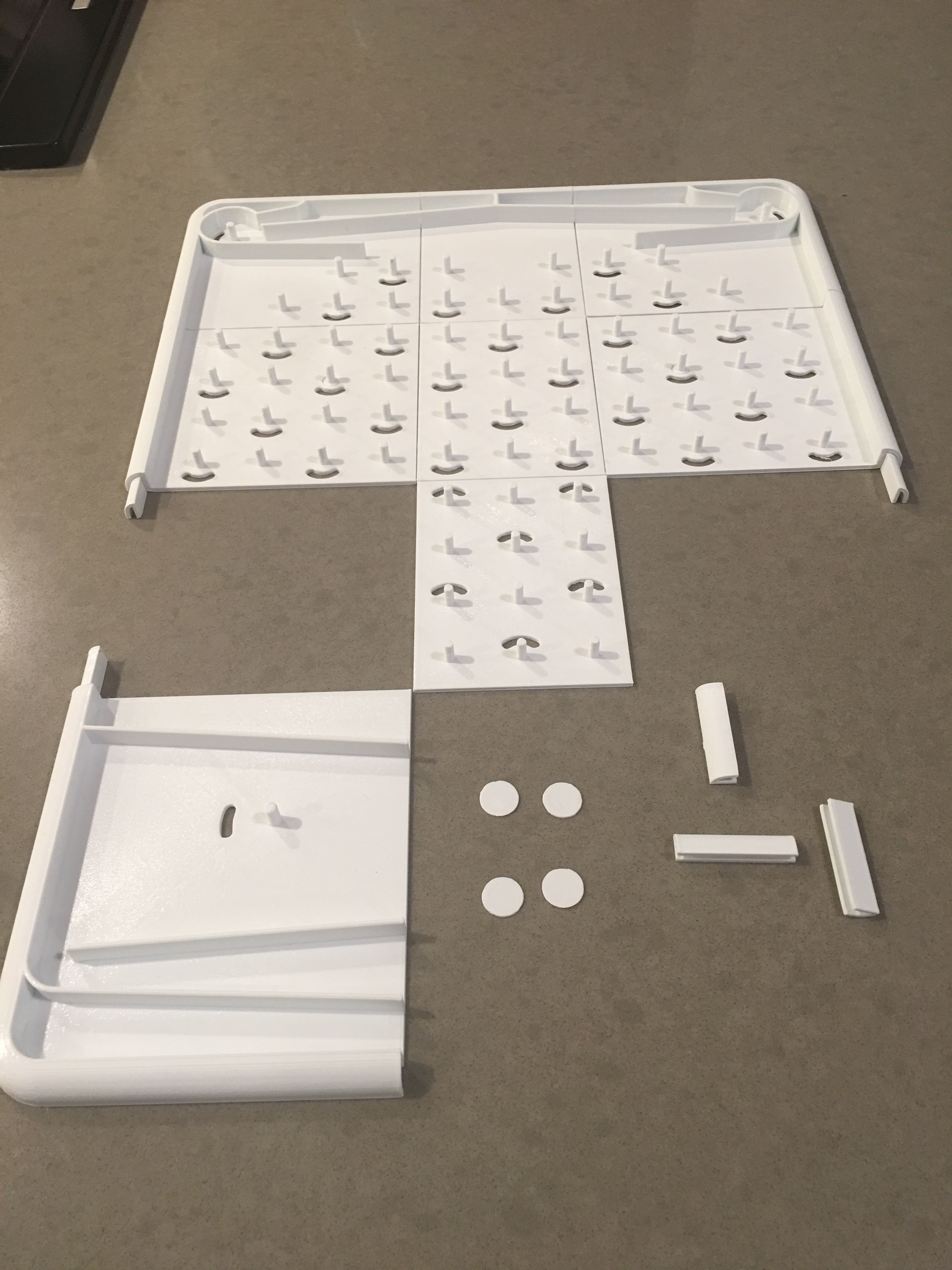
First off, I am still figuring out optimal print settings and configurations with the Ultimaker3 printer so take my experiences and ideas with a grain of salt.
As mentioned in the intro tips, I am not sure what is “good enough” quality for each component so I wanted to compare different print settings. I hope to use the production board to test swapping hand-printed ones with production quality ones and seeing how the print settings impact reliability of the board… maybe @paul can send us makers them early jk jk!!
I will try to keep this up to date with my experiences if others find it useful.
gear.stl:
I wanted to choose a simple but curvy starting point and gear.stl has some nice features in it. They will need to hook into each other so the quality might matter more with gears than other ones.
Basic
I started by printing this essentially as-is (open the file in Ultimaker Cura and print). I think with any 3d print you want to try to optimize for the model details you want but for this baseline print I wanted a literal “file open print”.
- Layer Height: 0.15
- Infill: 20%
- Support: yes
- Print time: 35m
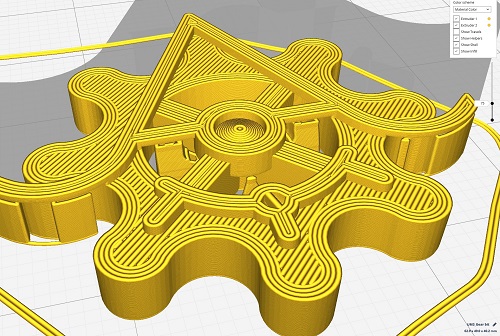
The results were non-optimal. For starters, the component has no good way of being printed without relying heavily on support structures. Secondly, the gear “details” (curves for the gear teeth) are using z-axis precision and the circular “tube” on the perpendicular axis is being printed “long ways” rather than as circular slices - also means theres support in the tube.
To be fair I did not try to optimize printing like this in any way – only did a print on low’ish quality 0.15 layer height and did not do any rotations. Without any cleanup and I did not even bother getting all the support out of it. You can see in the image the details of the rounded teeth getting ruined by support structure + printing ‘overhang’ to achieve.
Flat low quality
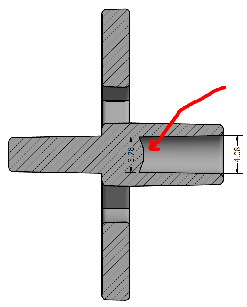
Next I rotated the piece to lay the “front” of the gear flat on the print bed. This means the printer can use x/y precision to print the curves and only really builds upward. Since the actual part has another extruded “pin” coming out of it from this, it was chopped off in this print. I printed the remaining model (the pin) along with this in case I want to attach it later.
Note: If you want to maintain the “pin” on the gear you will need to glue it on. I think in reality you would want to “split” the model up in the middle of the gear so that half the gear is printed on each side to provide more gluable surface area to combine them. Does this pin have more purpose beyond just having something to hold on to when adding/removing from board?
- Layer Height: 0.15
- Infill: 50%
- Support: yes
- Print time: 22m
The results on this turned out great. I honestly think this is going to be “good enough” quality to use in the real game, but may need some minor sanding particularly inside the tube to allow for smooth rotation. No touchups at all, no sanding or cleaning part after print
Flat high quality
This was the same as Flat low quality but with better print settings which takes longer to print.
- Layer Height: 0.06
- Infill: 50%
- Support: yes
- Print time: 1hr
This one turned out great as well, slightly better on the tube/pin than the previous print but may still need minor sanding. Not sure the additional 40m is worth it for so many components to print. No touchups at all, no sanding or cleaning part after print
board
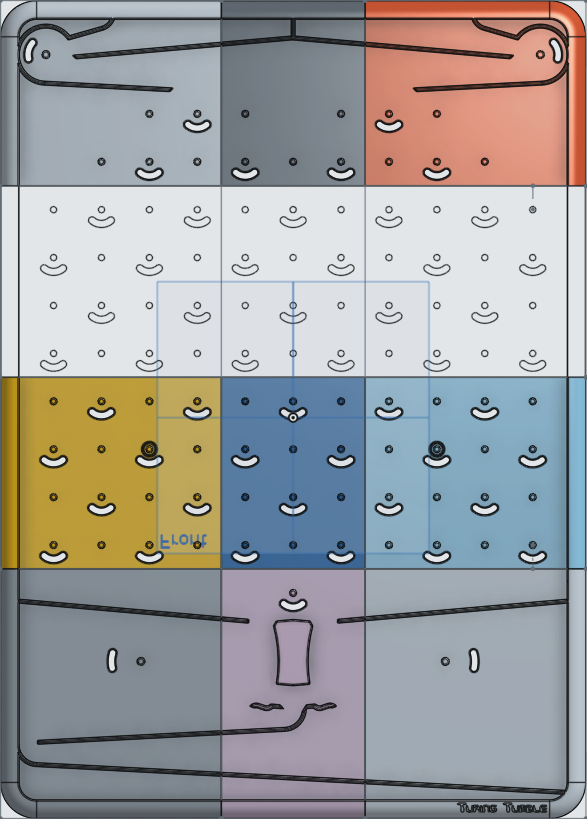
I have not looked into this heavily yet, but anyone have ideas for printing the board on smaller print beds? The new .stp files should help with modifications, but I was thinking about coming up with some way to print “sections” of the board and then gluing them back together. Another option would be to have them “hook” into each other if this is strong enough. If anyone has experimented with this already please let me know!
Hope this gives some starting points for others!
