Turing Tumble Community

Test printing with my Ultimaker3

First off, I am still figuring out optimal print settings and configurations with the Ultimaker3 printer so take my experiences and ideas with a grain of salt.

As mentioned in the intro tips, I am not sure what is “good enough” quality for each component so I wanted to compare different print settings. I hope to use the production board to test swapping hand-printed ones with production quality ones and seeing how the print settings impact reliability of the board… maybe @paul can send us makers them early jk jk!!

I will try to keep this up to date with my experiences if others find it useful.
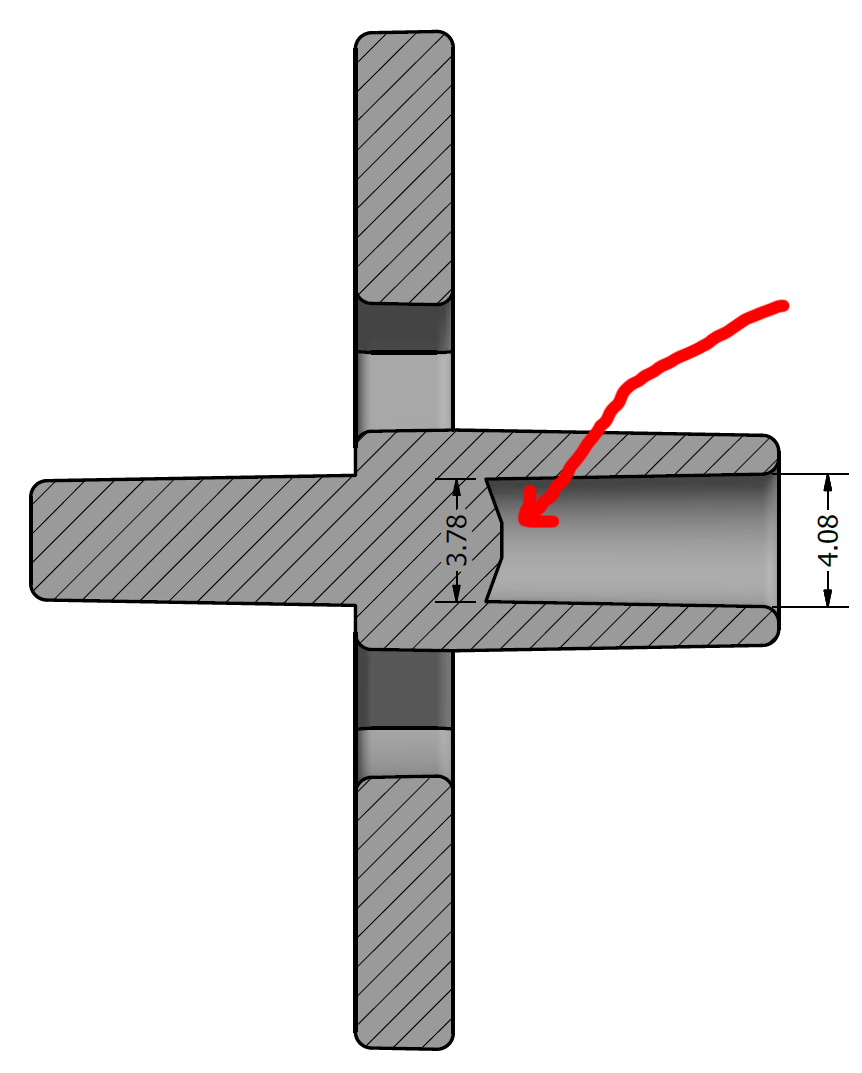
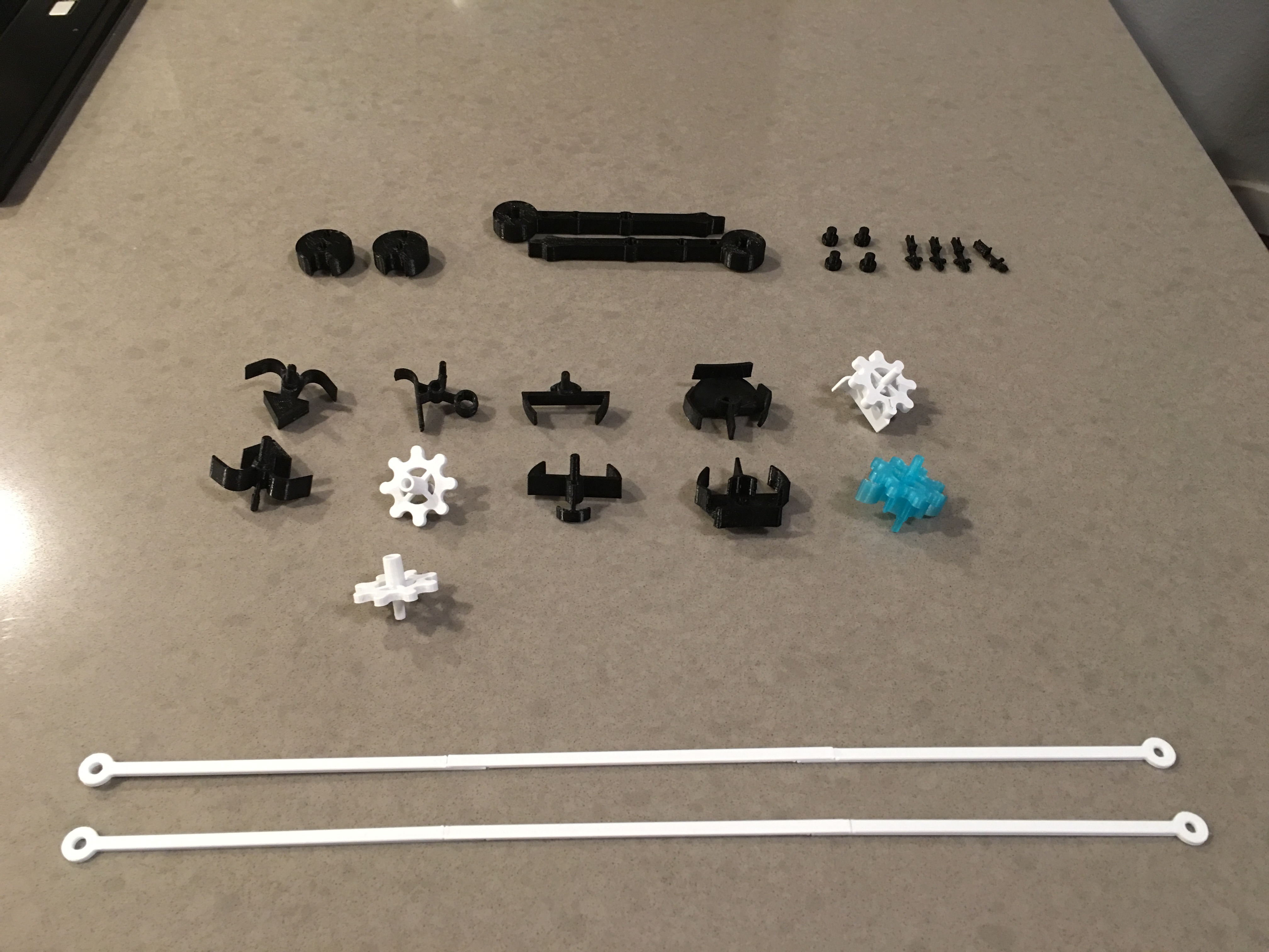
gear.stl:

I wanted to choose a simple but curvy starting point and gear.stl has some nice features in it. They will need to hook into each other so the quality might matter more with gears than other ones.
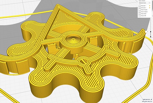
Basic

I started by printing this essentially as-is (open the file in Ultimaker Cura and print). I think with any 3d print you want to try to optimize for the model details you want but for this baseline print I wanted a literal “file open print”.

  • Layer Height: 0.15
  • Infill: 20%
  • Support: yes
  • Print time: 35m

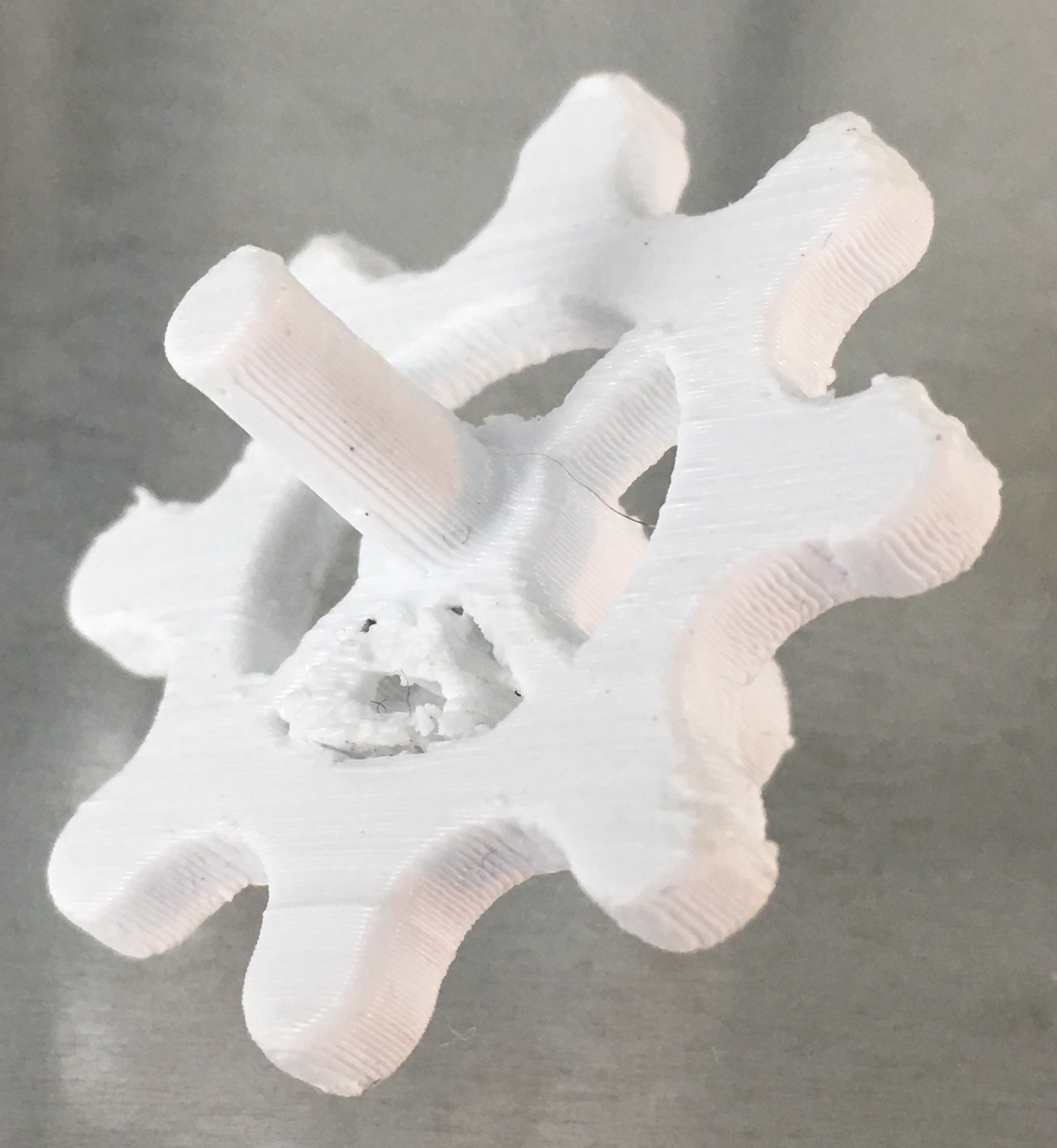
The results were non-optimal. For starters, the component has no good way of being printed without relying heavily on support structures. Secondly, the gear “details” (curves for the gear teeth) are using z-axis precision and the circular “tube” on the perpendicular axis is being printed “long ways” rather than as circular slices - also means theres support in the tube.
To be fair I did not try to optimize printing like this in any way – only did a print on low’ish quality 0.15 layer height and did not do any rotations. Without any cleanup and I did not even bother getting all the support out of it. You can see in the image the details of the rounded teeth getting ruined by support structure + printing ‘overhang’ to achieve.
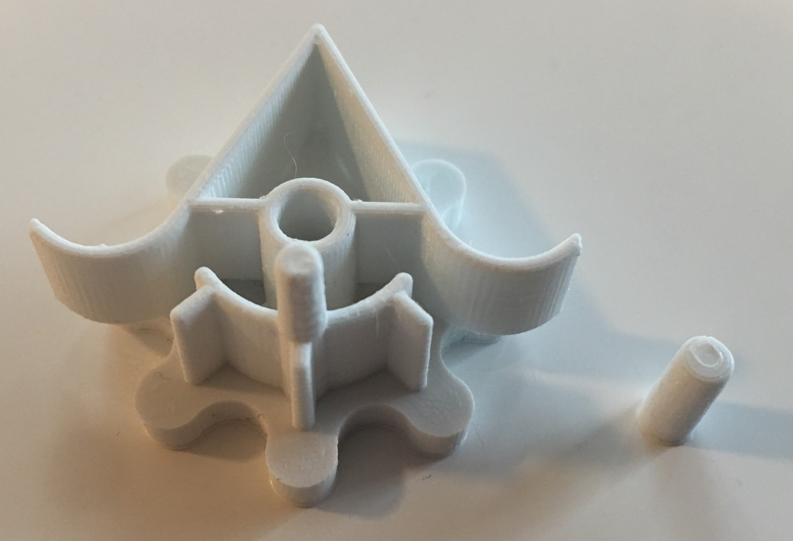
Basic

Flat low quality

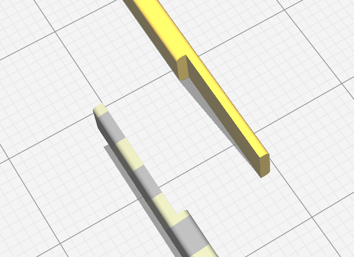
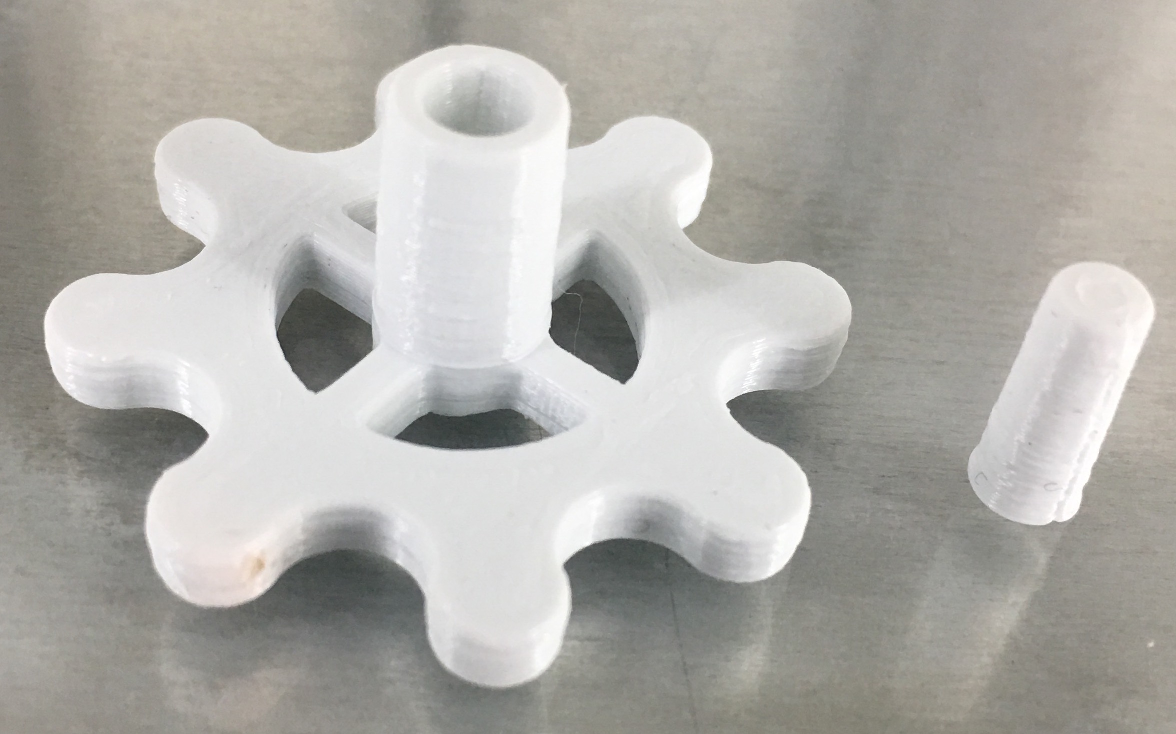
Next I rotated the piece to lay the “front” of the gear flat on the print bed. This means the printer can use x/y precision to print the curves and only really builds upward. Since the actual part has another extruded “pin” coming out of it from this, it was chopped off in this print. I printed the remaining model (the pin) along with this in case I want to attach it later.

Note: If you want to maintain the “pin” on the gear you will need to glue it on. I think in reality you would want to “split” the model up in the middle of the gear so that half the gear is printed on each side to provide more gluable surface area to combine them. Does this pin have more purpose beyond just having something to hold on to when adding/removing from board?

  • Layer Height: 0.15
  • Infill: 50%
  • Support: yes
  • Print time: 22m

The results on this turned out great. I honestly think this is going to be “good enough” quality to use in the real game, but may need some minor sanding particularly inside the tube to allow for smooth rotation. No touchups at all, no sanding or cleaning part after print
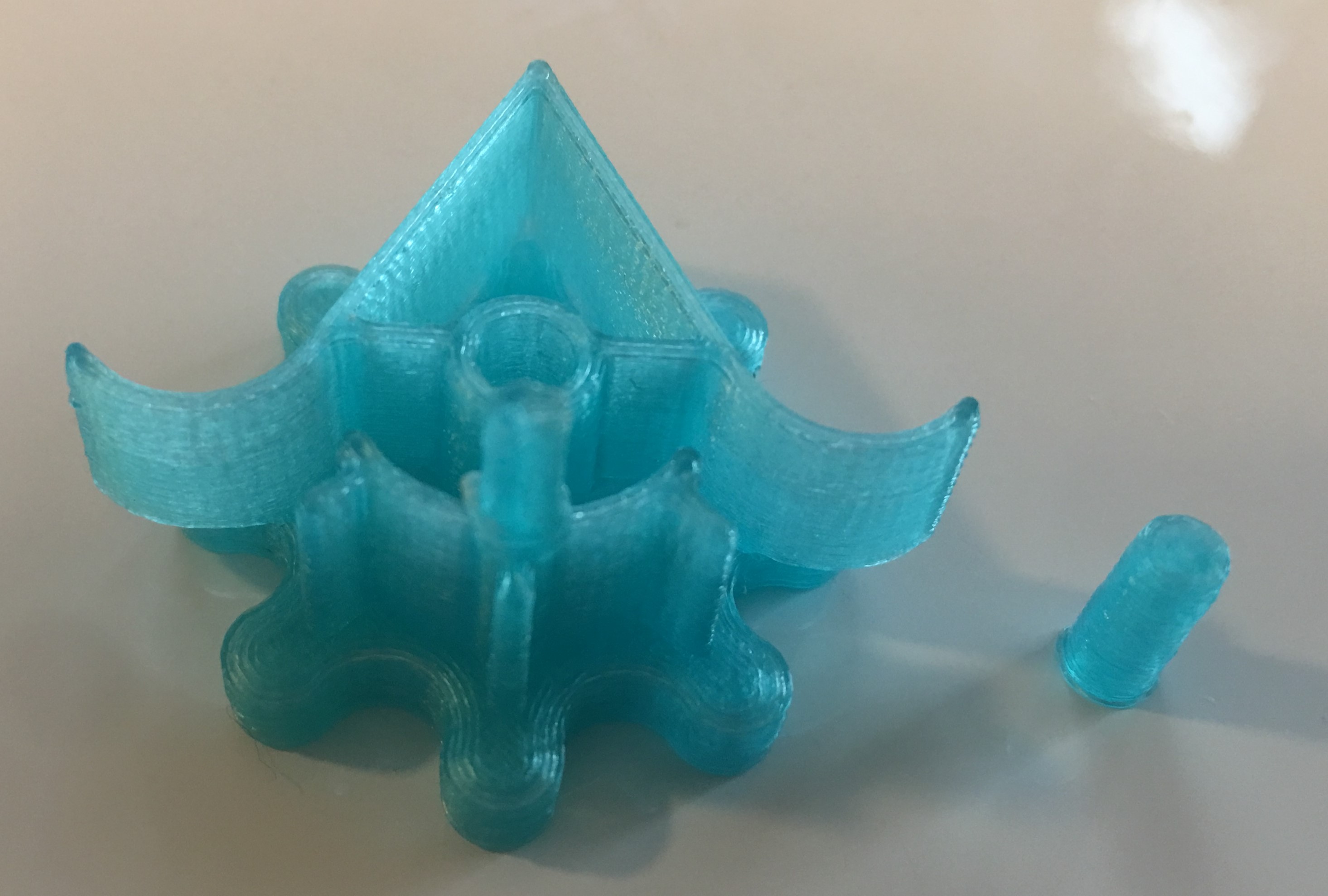
Flat-LowQuality

Flat high quality

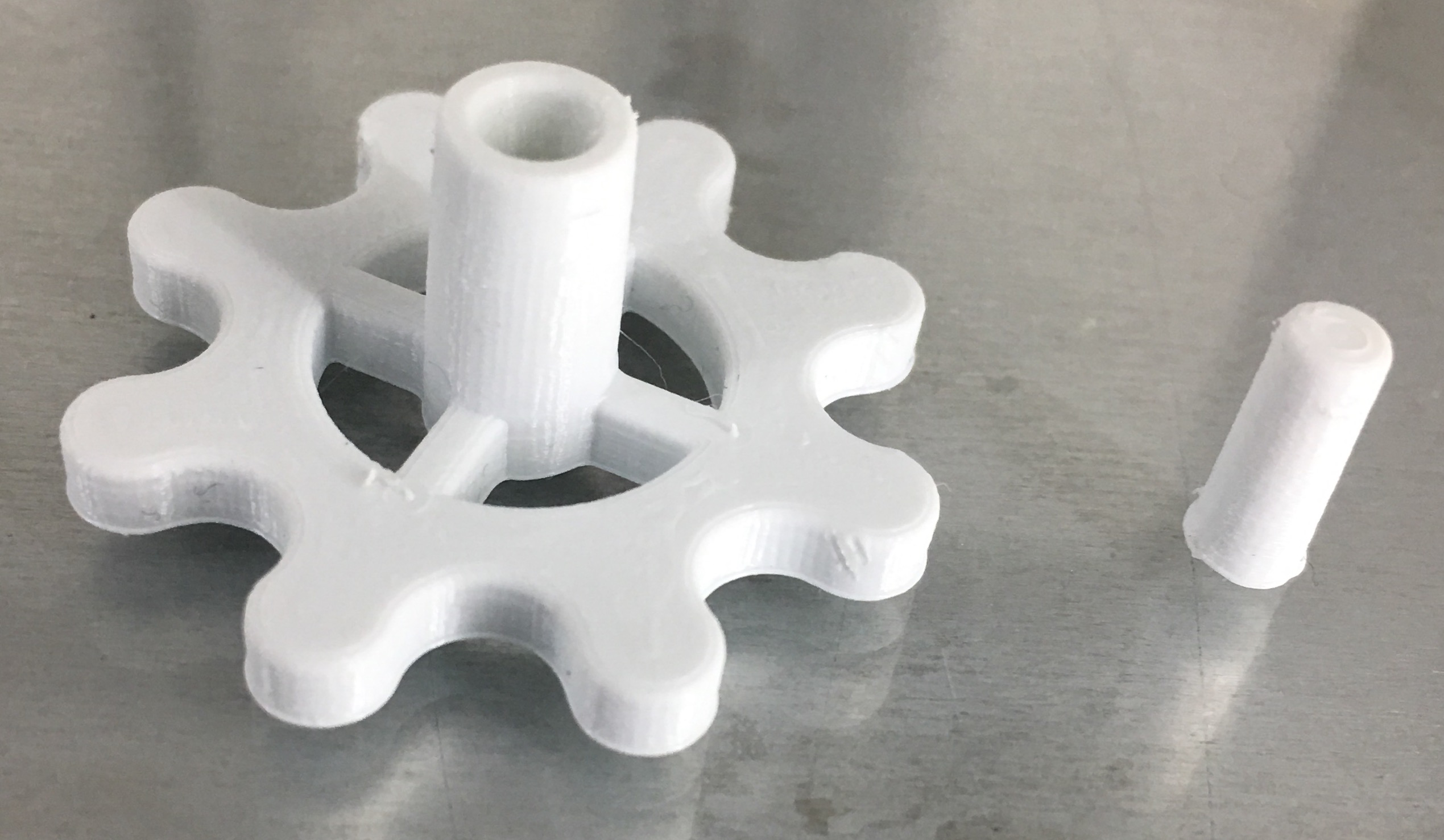
This was the same as Flat low quality but with better print settings which takes longer to print.

  • Layer Height: 0.06
  • Infill: 50%
  • Support: yes
  • Print time: 1hr

This one turned out great as well, slightly better on the tube/pin than the previous print but may still need minor sanding. Not sure the additional 40m is worth it for so many components to print. No touchups at all, no sanding or cleaning part after print
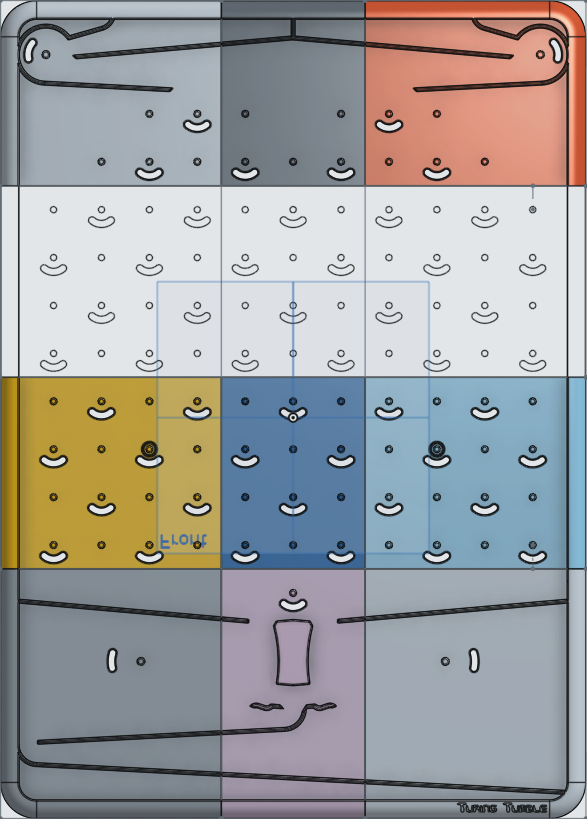
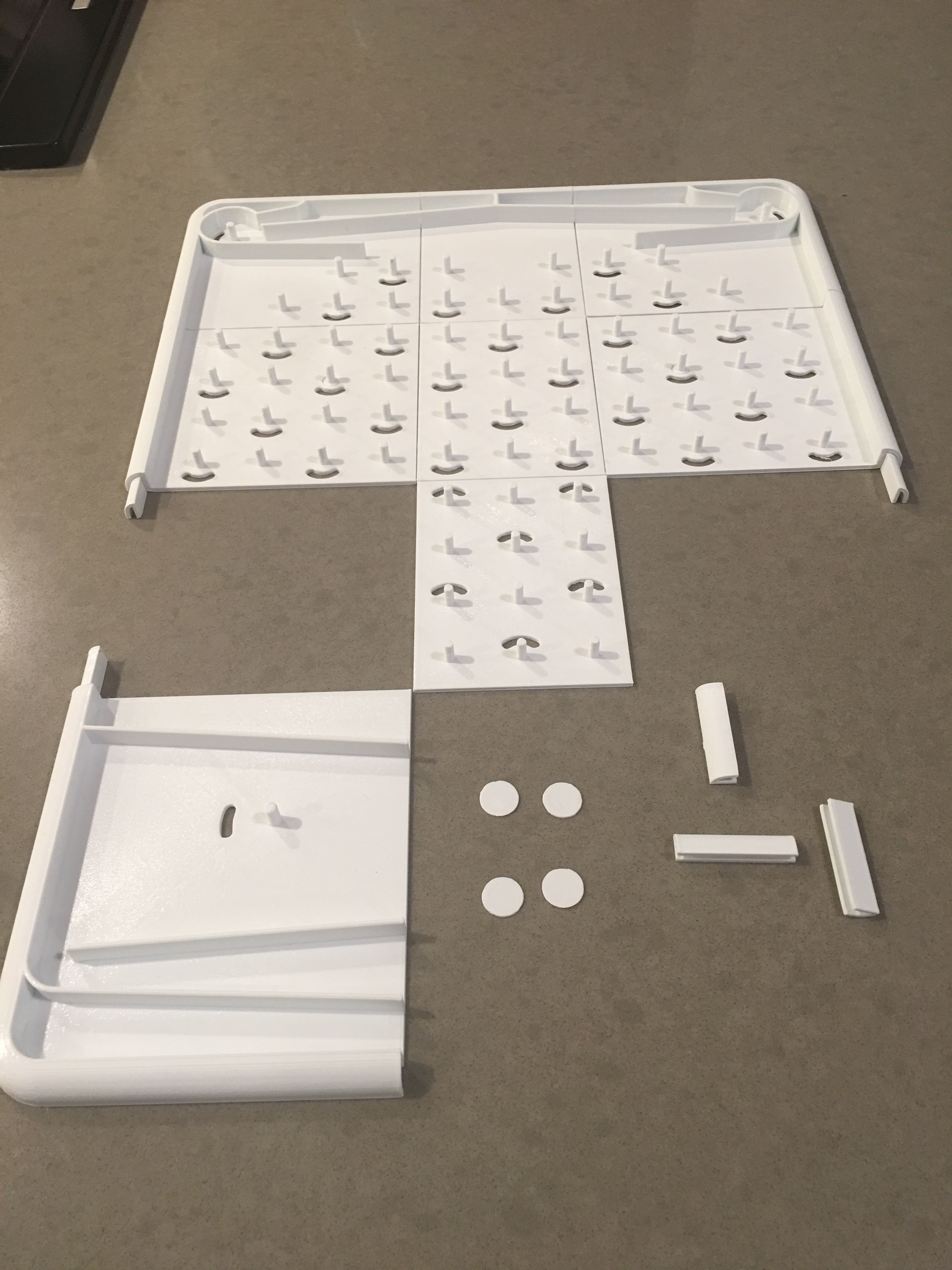
IMG_7335

board

I have not looked into this heavily yet, but anyone have ideas for printing the board on smaller print beds? The new .stp files should help with modifications, but I was thinking about coming up with some way to print “sections” of the board and then gluing them back together. Another option would be to have them “hook” into each other if this is strong enough. If anyone has experimented with this already please let me know!

Hope this gives some starting points for others!

3 Likes

Thanks for the feedback. It is indeed a very valuable ressource !

1 Like

This is fantastic! Nice work and great pictures. You made it super clear what you did.

Ok, I have lots to say:

  1. I like your idea of chopping the pin off for printing. You’re right, the pin is just for grabbing the part with your fingers and for turning it while it’s on the board. It will still function without it. Probably the most critical part to get right is the hole where it fits onto the board. The cleaner the inside of that hole can be, the better it will turn.

  2. A few more details you might not have noticed from the 3D models: I tried to design the gear and gear bit to turn with as little friction as possible, so you’ll notice there’s a little protrusion inside the hole. (See the picture below.)
    image
    The protrusion rests on the end of the board’s pin. It actually makes the gear bit sit slightly off the surface of the board to reduce friction.

The gear and gear bit have this protrusion, but the bits don’t. The bits rest against the board surface. It gives them a little bit more friction to help reduce bounce. I had trouble at one point with the bits flipping, but then bouncing back to the other side.

  1. I’ll get back to you about part samples. I ordered 200 sets of plastic parts for our own use that we’ll get pretty quickly after production begins.

Jesusaurus, looking at your flat prints, I think you’ve probably got it. This is great! I can’t wait to see what else you make.

Paul

I see what you mean with the protrusion, and this might be one of those things that the longer print times can do better. The layer-view of the gear bits show this little detail but its hard to say how that translates to the final print:
gearProtrusion

Anyways the other parts are coming along nicely, have not run into many problems. I am still printing a low/high quality version of each so that I can tell if it matters once I can test them.

gear bit.stl

This one had more support required because of the overhang on the ball catchers. They broke off easily and cleanly.

Here are some shots of two different prints at high quality (white) and low quality (blue). The blue one is translucent so the details are harder to see.

IMG_7352
IMG_7353

1 Like

These are great. I have no doubt they’ll work.

One more thing worth mentioning: the weight distribution of the gear bits is different than the weight distribution of the bits. The bits are meant to be top heavy. The big arrow on top adds weight to the top of the part so that when it flips left or right, it stays there.

The gear bits, on the other hand, are balanced. That chunk of plastic on the bottom, behind the gear, shaped like a smile with three fins coming off of it, is just there to add mass. The gear bits need to be balanced so that a single ball can turn several gear bits. If instead they were unbalanced like the regular bits, a single ball wouldn’t be heavy enough to turn several of them at once - the force needed to lift the top-heavy parts would be too great. Because of this, gear bits can’t be used on their own. You have to have at least two connected together. A single gear bit doesn’t hold its position after a ball goes over it. It often bounces back the other way unless it’s connected to another gear bit on the board.

This is cool - thanks for sharing!

I have printed almost all of the parts at least once, and have a few things I want to wrap up in this post. For starters, the only parts that I had trouble printed due to size are: connector, board, board supports. I will go through my thinking on each of those components below, but first: tada!!
CompletedParts

Now onto the hard stuff…

Connector

This was simply too long to print in a single go, and rather than breaking it in half I made three parts (reasons to explain later) one for each end, and a middle part that just connects them. Since they are quite long, I edited the model to make a new one that broke it up and added some “glue areas” to the ends of the parts. These are basically just notches that extend from the ends to glue together…maybe someone has a better idea? NOTE: these are not just notched into the split parts, but need to extend from one side to go into the other to keep total length correct.
tt-connector

Board

The board is huge, and wont print easily. I edited this as well to cut out “panels” of the board but have no idea how these will work (how to connect/glue them, will it be strong enough, smooth enough).
tt-board-split

@paul The middle panels should be identical vertically, any chance (with longer connectors) they could be duplicated more than twice in the middle to extend the playable area? Not something I aim to do, but curious if this would work and one of the reasons I split the connector into 3 parts (longer middle part could be used with larger board).

I still need to print this to see how they turn out, each panel takes over 4 hours on lowest quality setting :sob:

Board supports

I think these should be able to be broken up in a similar way to the board, with maybe two prints. My biggest concern is keeping the original design the way it was, however printing the details on each side of each support part is difficult in the printer so I may skimp on some details on the first print. If anyone has any other suggestions here let me know, otherwise you could always print each “half” of each support (broken up) and glue it all back after print.

3 Likes

Nice! The way you cut up the board and the connector was very clever. I think you could totally make the board taller if you wanted to.

Any chance you’d be willing to post the STLs or STPs of your modified parts? I think this could be extremely useful to others trying to 3D print their own games. You’re blazing a trail and you’re doing it with style.

I’m excited to see if it works once all those panels print!

Sure here are the board files, as well as two clips I made for hooking them together

Board[1-9].stl - these are sections of the board that should be printed. The Board4.stl, Board5.stl, Board6.stl should be printed twice. Make sure to rotate them to be flat, and clip off the back rounded edge that goes below the surface of the board.

BoardEdgeClip.stl - this is a little triangle that fits into the edges of the outer board to give it some stability…I plan on trying to glue these on edges.

BoardMidClip.stl - this is a little flat circle that I plan on gluing to the back of the middle sections to give it some more stability.

3A03F62B-F037-4915-9BAF-512143AA82F0

OneDrive download:

3 Likes

could you please post stls of your Connector parts? thanks.

Could you please post the stls for your Connector parts? Thanks.

great work! I’m about to embark on this print and your research/mods will really help!

Can you upload your files to Thingiverse?thanks.

Could you please post the stls to Thingiverse? Thanks.