I already showed Turing complete machine with TT parts. It can be seen on the link below.
https://community.turingtumble.com/t/counter-machine-in-3360-lines-tt-vba/705
But it is very large and difficult to understand. In addition, the gear bit chain used for it is impossible to realize.
By creating a special instruction set this time, I made the TC machine executable at TT.
I made it in Excel’s VBA, In order to grasp it, a synthetic image of TT was created.
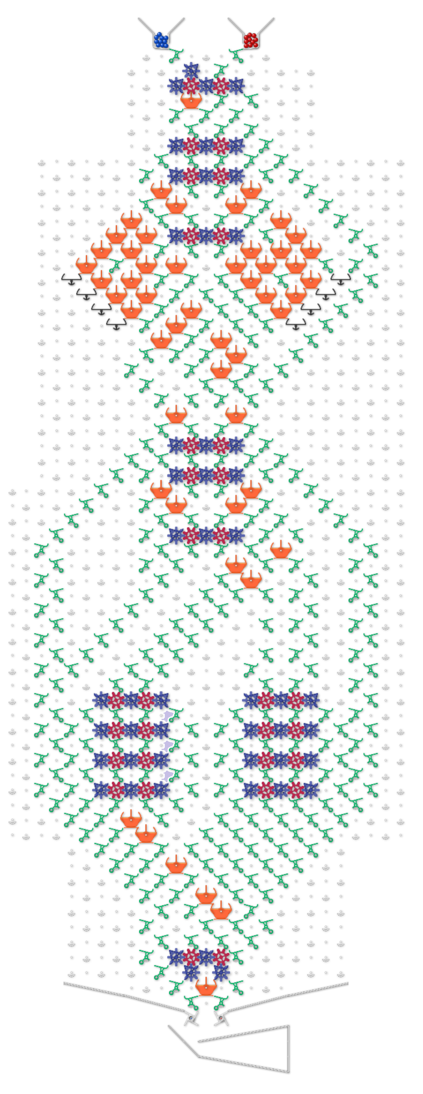
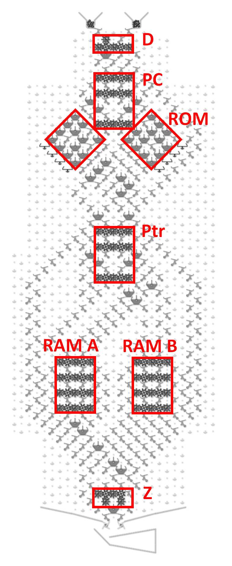
It includes six sets of gear bit chains as shown below.
D … direction of program counter
PC … program counter
Ptr … pointer shows which RAM (but sequential access!)
and which direction selected
RAM A … left side 4 bit RAM
RAM B … right side 4 bit RAM
Z … reserve bit for zero check
There is a ROM area on the left and right of the PC.
For the program, it is necessary to configure ROM and RAM as initial value.
When parts are set in ROM as follows,
If RAM A is odd, “F” enters RAM B,
If RAM A is even, RAM B remains “0”
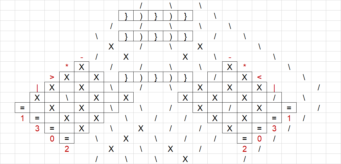
Express this as below for easy viewing. Note that the order of ROM is different from the execution order.
|-|<|
|=|||
|*|=|
|>|-|
In the initial state, “D” points to the right and PC is 0. That is, the first ball executes “<” on the upper right.
And Ptr points to “A-”.
This, or “>”, is a conditional branch instruction. Details will be described later, but if the referenced RAM A is 0, we will pass through.
That is, PC indicates “|” directly below. Also, Ptr moves 2 as a side effect, and it points to “B-”.
Since TT can not read nondestructively as it is, side effects occur.
The next “|” is NOP. That is, it shifts to “=” below without doing anything.
“=” Is HALT, that is, the program stops there.
Here we consider another case.
If the destination of Ptr is “X+” or if RAM A is not 0, “<” in the upper right inverts D and branches to the left
(In other words, it passes “X-” only when X = 0). As a side effect, subtract 1 from RAM and Ptr moves next.
The PC points to “-” in the upper left. This instruction decrements Ptr by -1.
Ptr is a variable that specifies RAM and its operation and specifies “A -”, “A +”, “B -”, and “B +” in this order.
According to the previous command, Ptr indicates “A +”, so it returns to “A-” by “-” command.
Then execute the above command in the left column.
Since it can not go further up this time, it returns to the “>” at the bottom.
“>” In the lower left shifts to the adjacent column unless RAM A is 0 as well as “<” in the upper right.
Go from “-” in the lower right to “<” in the upper right and repeat < - > - < - > - … until RAM A becomes 0.
After RAM A goes to 0, going to “<” in the upper right will result in NOP-HALT as I just wrote.
On the other hand, when RAM A reaches 0, when reaching “>” in the lower left, go straight there and go to the upper “*”.
At this time, Ptr becomes “B-” due to a side effect.
“" Adds or subtracts RAM according to Ptr. That is, since this time is “B-”, RAM B changes from 0 to “F”.
For example, if “A+”, 1 is added to RAM A. After that, shift Ptr by +1. This is actually the same as the side effect of “>”.
By skillfully combining "” and “-”, it is possible to arbitrarily change the values of Ptr and RAM.
After “*” execution, it reaches “=” above and stops.
Here, write “>”, “<” in further detail.
The first blue ball passes through most of the blocks and reverses only the last “Z”.
Furthermore, by falling to the right side, the next ball becomes red.
The red ball reverses “D”, ignores the PC and always performs “*” operation.
Ptr points to “X+”. Or, if the RAM is not 0, the next ball is blue.
That is, the PC was reversed.
On the other hand, when the condition of “X-” and 0 is caught, the next ball is a red ball.
Since the red ball reverses “D”, it means that no branching will occur as a result.
Also, the next ball inevitably becomes blue.
In theory, RAM and ROM can be increased any number.
It does not matter the physical limit of the Gear bit.
The attached Excel file also includes examples of counting and addition.
Thank you for reading.
TT_CPU.xlsm (62.5 KB)
