Note - this is not about Turing-completeness, but about how to simulate a (finite) computer. This construction is actually buried in pieces in an earlier post on how to compute an arbitrary Boolean function. I’m extracting it into this new post, explaining it better, and incorporating some pictures. Apologies for the repetition - but I’d appreciate it if others can verify that this works, or point out any problems with the construction.
This construction borrows ideas from @Jcross ingenious cellular automaton simulation, and will hopefully help people understand and appreciate that more complex construction better, since assuming it works (I think it does), it shows that TT is Turing-complete (allowing unbounded computation) assuming a ball can drop through infinitely many gates to trigger another ball.
So, how do we simulate any computation on a finite computer? Any computer can be represented via a finite number of bits, giving the contents of the memory, the registers, the instruction counter, etc. Suppose there are N such bits total, and that they are stacked into a single register on the TT board. (So, for example, if the computer had eight 16-bit registers, we’d have a stack of 8*16 bits at the top representing their values. Below that might be the finite memory contents (the program to be executed), the program location counter, etc. All one tall stack of bits on the board.)
Then after execution of one “step” of a program, or one cycle of the machine, depending on the level of resolution of our view of the algorithmic process, the bits arrive at a different state. Hence, a single step of computation on such a computer can be viewed as a function f from N bits to N bits, and an entire computation is the result of applying that function repeatedly (i.e., composing the function with itself sufficiently many times to achieve a fixed point (until the program has halted and no more changes are occurring).
We can show that for any number of bits N, and any computation function f from N bits to N bits, a finite number of pieces of TT can be arranged so that a single ball drop will cause the change of a collection of a stack of N gear bits to reflect the application of function f. By triggering more balls, the device can apply f repeatedly to walk through the state changes describing the trajectory of the computation.
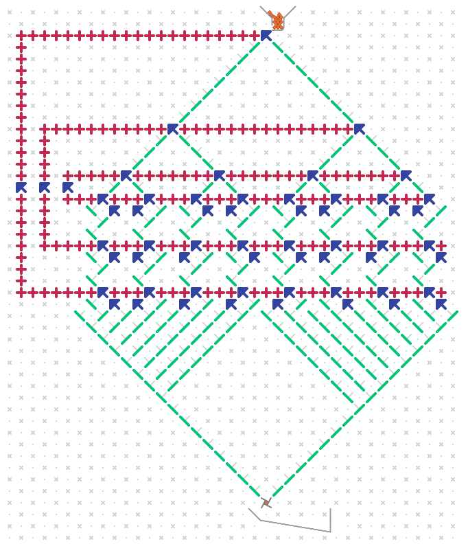
Instead of representing the computer with a stack of N bits though, we’ll have lots of duplication, and represent it in a binary tree structure with N levels made up of gear bits. The k-th level will have 2^k gear bits, all geared together so that they always show the same value. Hence, there are effectively only N different functional gear bits, and exactly 2^N configurations of these gear bits, although the total number of them is much more (2^N-1). If the gear bits are packed too closely, then there may be as few as N+1 exit points from the tree, but if they are sufficiently far apart, then we can ensure that there are exactly 2^N distinct exit points, and can also extend the 2^N paths from the bottommost gear bits to ensure that the ball may arrive at one of 2^N distinct locations each separated by at least, say, 10 spots, which will allow subsequent gates to be placed below each path without interfering with gates placed below other paths. Below is an example of a tree of height N=3, with 2^3 = 8 paths extending from the bottom of the tree. Due to space constraints, I’ve only shown it with little separation between the 8 paths at the bottom, and this wouldn’t work with the rest of the construction. But by making the tree larger (but the same number of levels N = 3), we could have any separation we’d like.
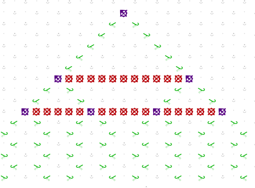
Assume a tree with N levels, and some particular setting of those bits corresponding to a snapshot of a computation. Then a ball routed to the top of the tree will be directed along one of the 2^N distinct paths. From there each path will continue straight down, and a ball so routed will pass through N latches (puzzle 28) each of which affects a possible change in the gear bits in the binary tree as follows: By choosing either to place a “write-0” or a “write-1” latch in the path, the ball can set the bits across a given level of the tree to a 0 or a 1, respectively, via a connected chain of gears. Here is an example of a ball about to set the bottom layer of the tree to the value 1, in a tree with N=2.
(The astute observer will note that the location of the blue ball is inconsistent with the gear bit settings above it, but this is for illustration purposes only.)
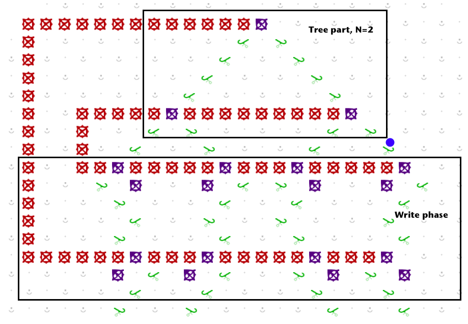
In order to avoid having gear chains cross paths, it is necessary to set the bits in the binary tree in reverse order, so that after exiting the tree at the Nth bit, the first write will affect the Nth level of the tree, the next will affect the N-1st level, and so on, so that the last write encountered will affect the very top gear bit in the tree. This forms a collection of nested “C” shapes as in @jcross cellular automaton construction. Refer to the picture above.
In the picture, f(00) = 01, since if the tree bits are both set to 0, the rightmost path is chosen, and then the ball passes through a write-1 to set the last bit to 1, and then through a write-0, to set the first bit to 0.
Because any sequence we’d like of write-0 and write-1 units may be placed along each of the 2^N paths, any computation function f can be specified. And, after one pass of the ball through the tree with bit pattern x and subsequent exit path corresponding to pattern x, and write bits programmed according to the desired value f(x), by the time the ball hits the lever to trigger another ball, the tree pattern will show f(x) - i.e., one step of computation will have been executed. To stop the computation, particular output paths can terminate with an interceptor instead of continuing on to trigger another step of computation.