Turing Tumble Community

Proof of Turing Completeness?

Thank you for reading my paper! Actually, I think that the paper is too short to understand it. I want to try to write up the explanation. But it will probably take a long time to that, and please give me some time.

And I’m interested in your ideas that simulating Counter Machines or Rule 110 on TT. I can’t wait to read your proof. :grinning:

1 Like

OK - I think I understand where you’re heading now. Seems to me that with either approach (sliding strip of bits to represent the tape, or infinite diagonal or column of bits to represent memory and unbounded numbers), a significant challenge will be to implement an arbitrary finite-state control. With your intended design, I think there may be an additional challenge also in being able to increment, or decrement, a number as desired. At least the way I’ve been solving problems in the puzzle book, each design requires either a fixed layout that adds one to a binary number, or a different layout that subtracts one, and these use fixed ramps that point in opposite directions. A mini-puzzle might be to create a mechanism that adds one to a number on receiving a ball from one direction (say, a blue ball), and subtracts one on receiving one from a different direction (say, a red ball). Actually, if you couple two such counters with a finite control, you’ve got a two-counter machine, which surprisingly is powerful enough to simulate a TM, so we’re done.

I can’t say I follow all the theory here about Turing Completeness, but I believe I have designed a “metapixel” that can implement any 1D elementary cellular automaton. This includes Rule 110, obviously, so if it works I guess it would constitute a practical proof? Well in any case it’s the best I can do because a formal proof is out of my league at this point.

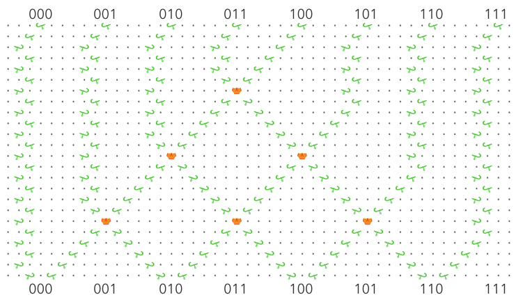
I’m not sure how well it handles the infinite extent requirements, but it lays the cells out vertically, so the width is smallish and fixed. The height varies with the number of cells being simulated, and can in theory be extended indefinitely. It requires only one ball per generation, and side/color is irrelevant. There will be some issues with edge conditions at the top and bottom, which could be crudely solved by padding. There also may be a proper solution to make it behave like a ring, but I haven’t fully considered that yet. It could involve either some fanciness with ball side/color or some VERY long strings of gear-bits.

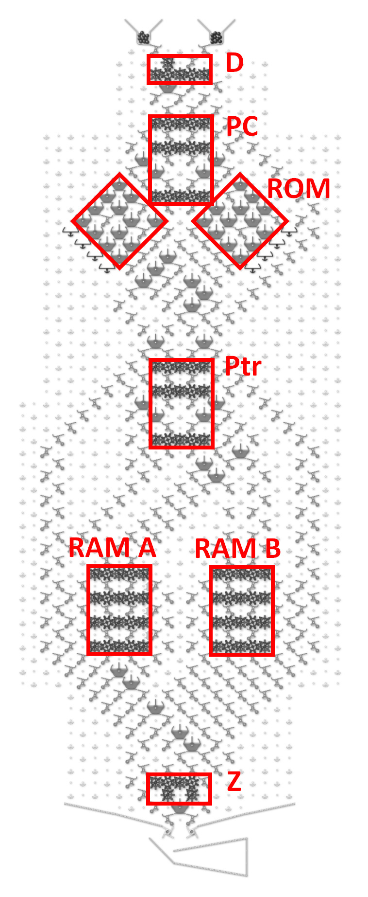
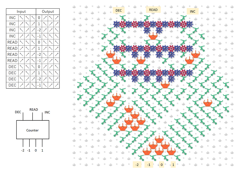
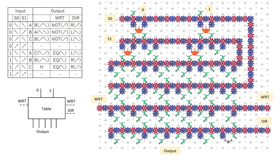
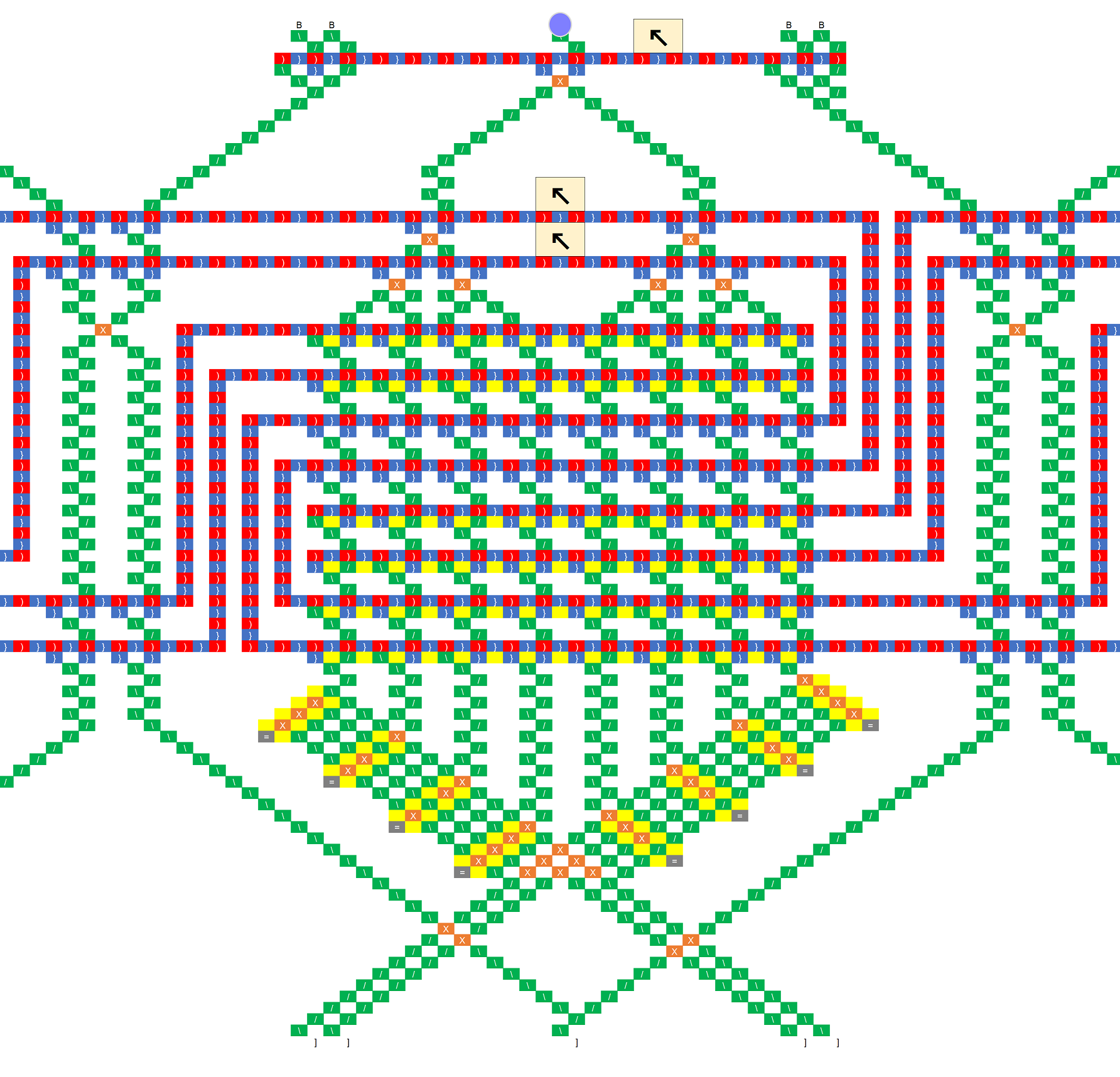
Okay, on to the solution. The mechanism effectively stores a 3-bit register, using horizontal ball position to encode its contents. The core operation that can be performed with this register is to shift one bit onto the end of it, moving the rest one position left, such that ABC become BCD. This shift operation is accomplished by the following unit (there are a lot of parts so I’m using a schematic representation of the board):

shift-unit

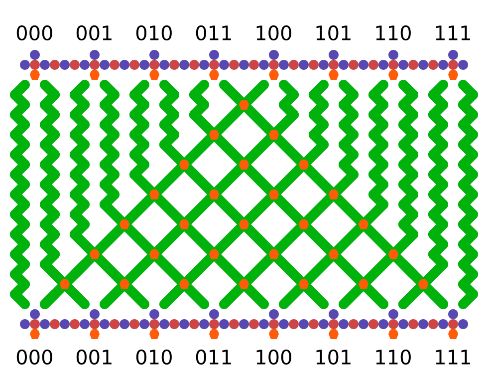
So regardless of which position the ball arrives in, the value from the set of gear-bits at the top is non-destructively read and the ball is routed such that its value is shifted onto the end of the register. In this way, the running value of three cells can be stored. To implement the CA rule, we route the ball through units that perform a destructive read:

write-ops

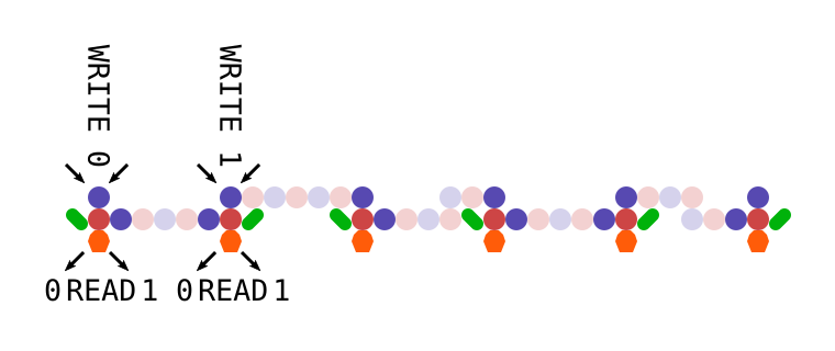
There are two types of units, one which writes a 0 and one which writes a 1, but either will use the prior value of the bits to route the ball in the same way as the units above. As you can see, they can be arranged on the same spacing, and any combination of units can be geared together without interfering with their function. By placing eight writers into the appropriate positions, we can implement any elementary CA rule.

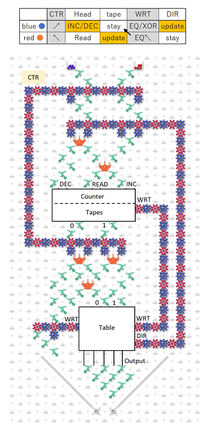
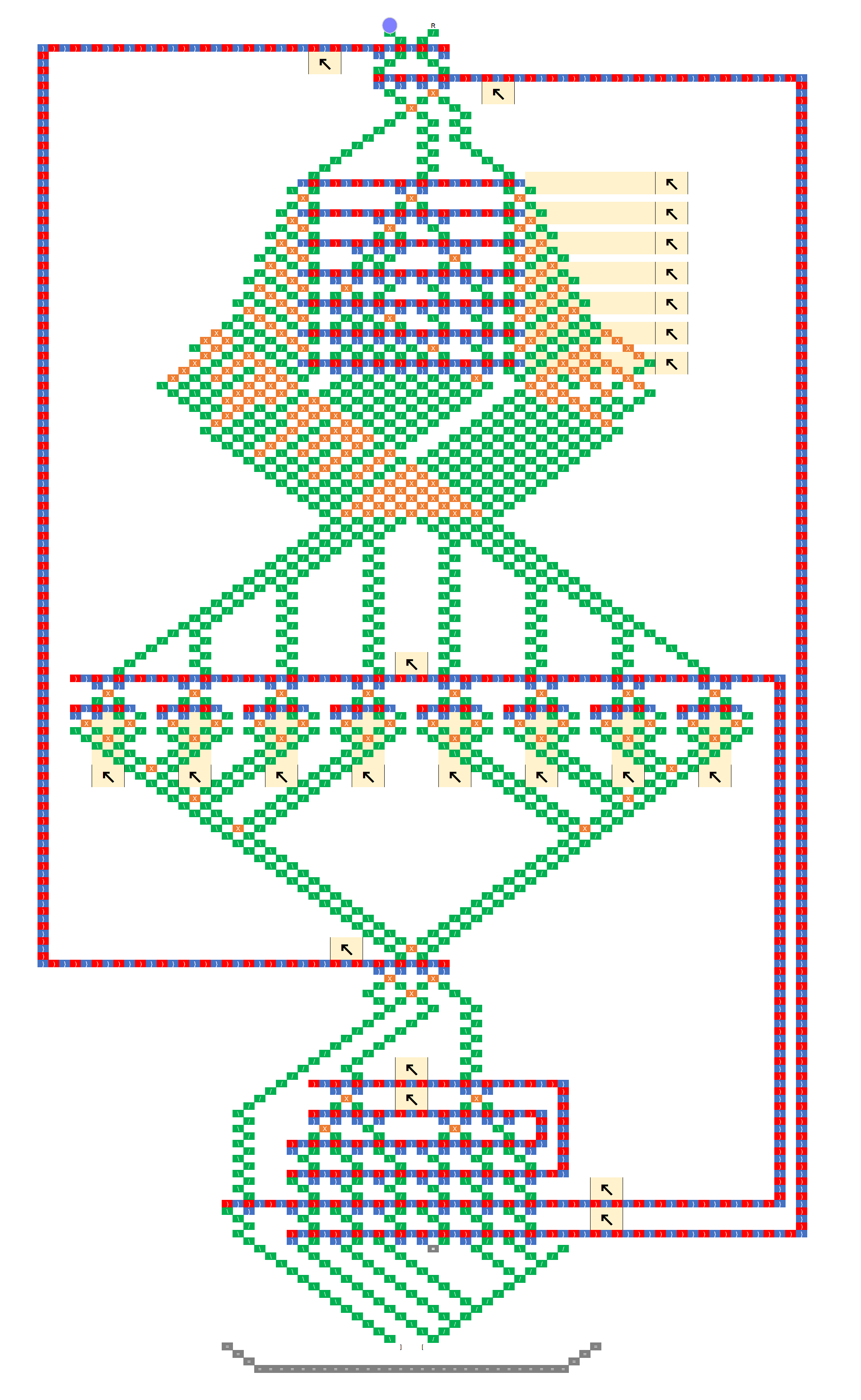
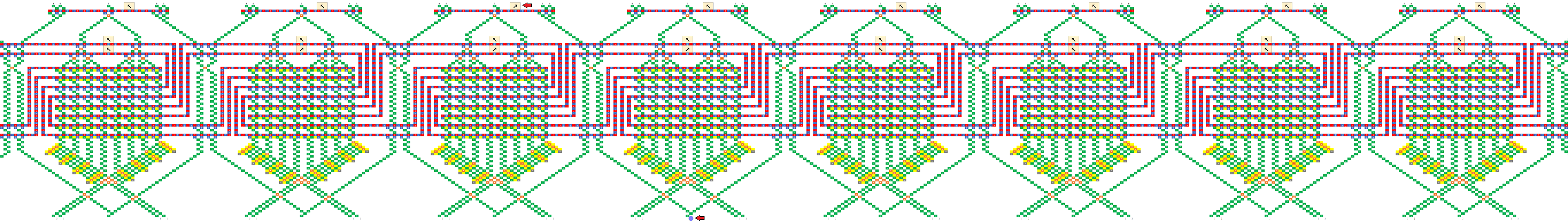
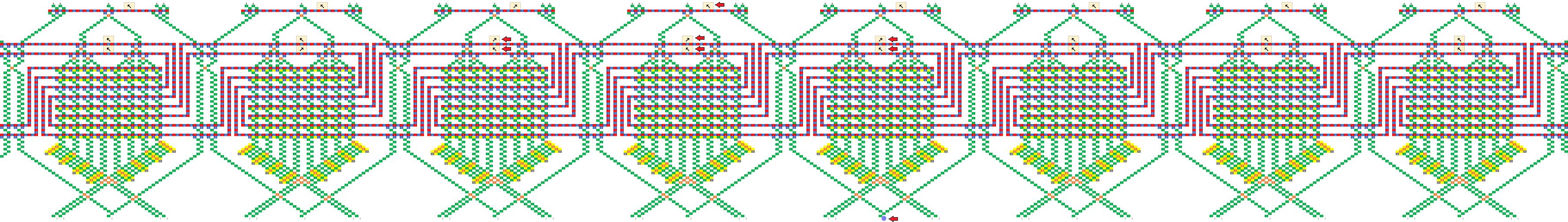
The remaining step is to arrange these units in a continuous chain and propagate some information upward as the ball drops (and we can’t cross gear chains (yet)). This is done using a topology of interlocking C shapes. Each C is a long chain of gear-bits representing one cell in the automaton, with a read stripe at the top and a write stripe at the bottom. Half the cells push up information on the left and half on the right:

rule-110

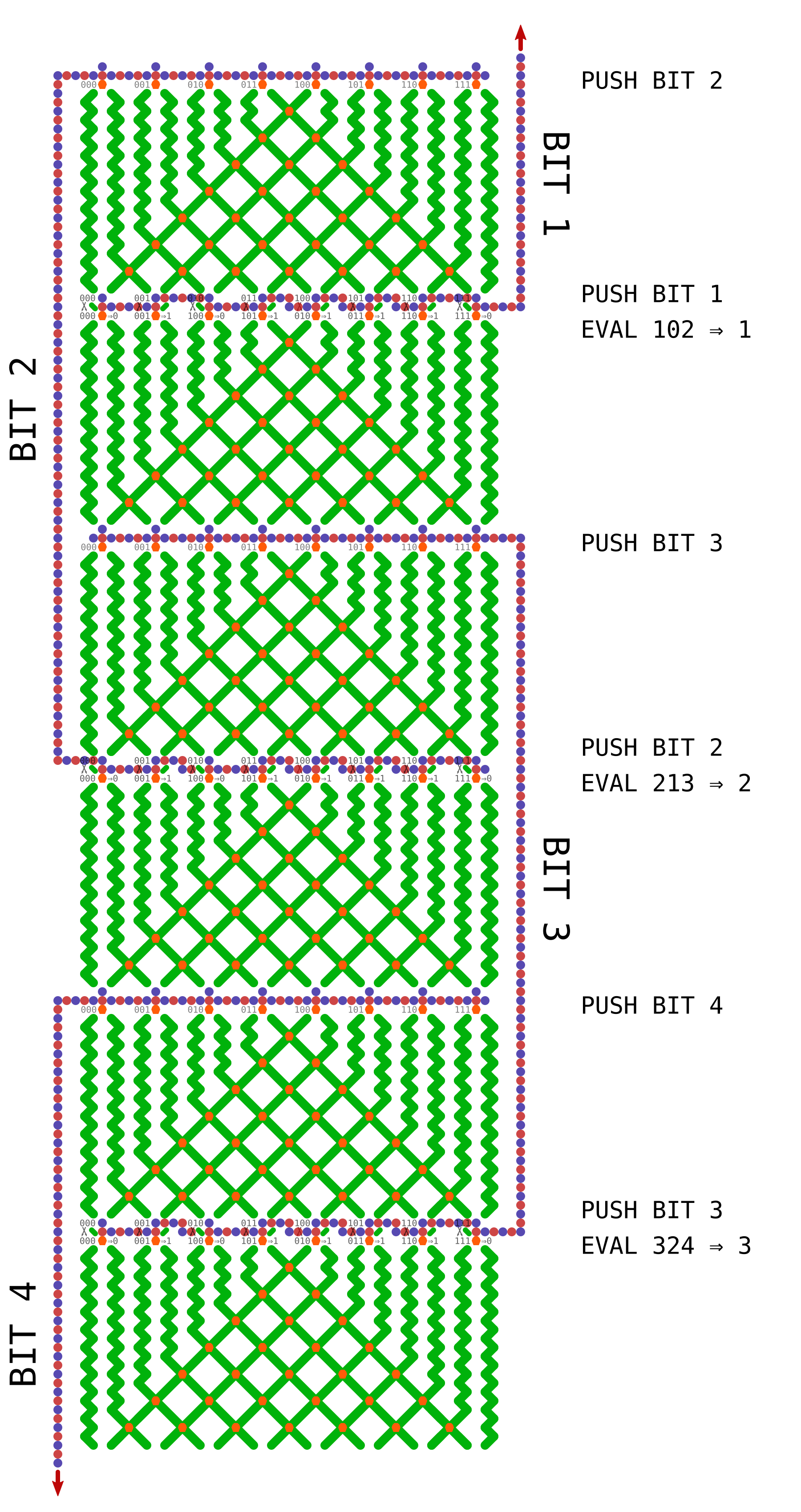
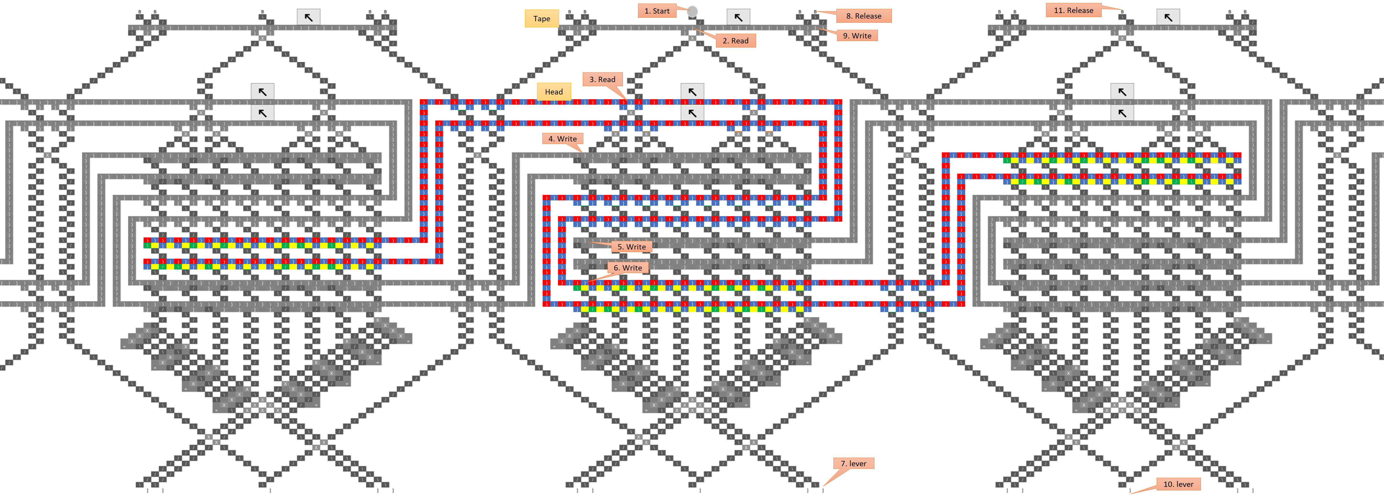
That’s a big image, but metapixels do seem to spread out… I just realized I probably could remove some space between parts and make this about half the size, but I drafted it with extra room just in case. Anyhow, because of the order in which the bits are pushed onto the stack, the rule isn’t laid out in the usual way. Each time it’s evaluated, the order of the cells is BAC => B, CBD => C, DCE => D, etc, so the current cell and its “left-hand” neighbor are always switched. It’s pretty trivial to map the rule, and I figured it was easier to do that than something like using multiple types of routing panels to get the order into the canonical form each time.

So, I’m fairly sure this would work but would appreciate more eyes on it. Also, is there a simulator that can handle arbitrarily large boards? That might come in handy if we’re going to continue speculating about theoretical problems.

EDIT

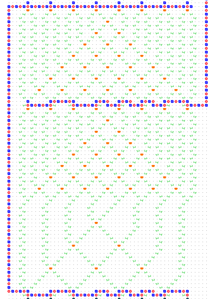
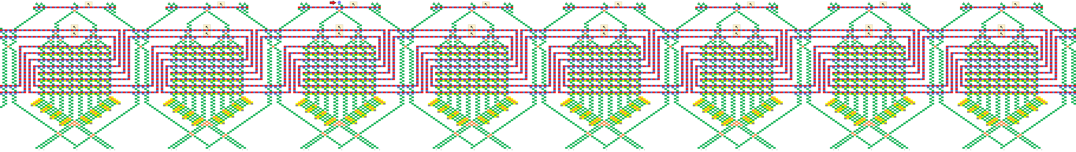
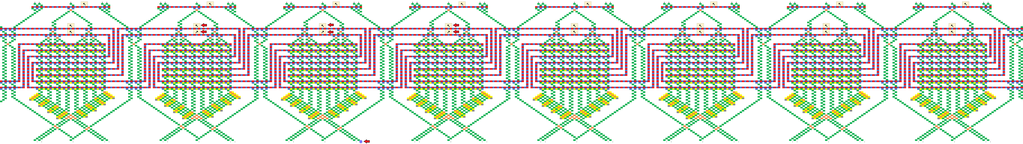
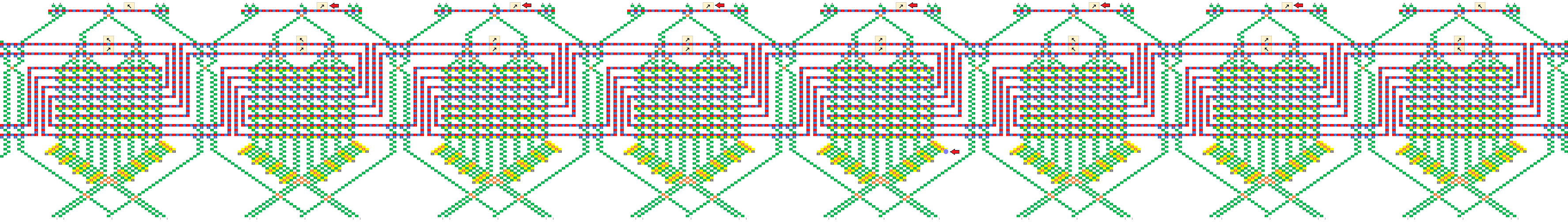
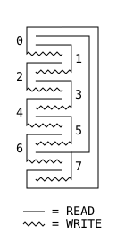
I think making it into a ring works out okay, although it involves very long chains. But hey, if we’re imagining infinite boards we can imagine constant friction too. Here’s one topology that I think would work, forming a ring of eight cells.

ring

This game is keeping me up at night Paul! It said “addictive” right there on the box, but did I listen?

6 Likes

Regardless of whether this is right or wrong, or works or not, this seems ingenious. There is a lot here to digest, and I’m trying to understand it, and my head hurts :slight_smile: I’m a bit confused and fuzzy about the high-level idea though. Here are some basic questions which may help me: Let’s suppose that you are only simulating the evolution of a fixed-length string (I guess we assume for the purposes of rule 110 that non-existent neighbors at the ends are treated as 0s).

  1. Before any ball drops, how is the state of the initial string represented? Is each “C” chain of gear bits flipped to 0 or 1 to indicate the value of the corresponding bit in the input?

  2. When a ball drops in, what column does it drop into, and how is that achieved, both for the first, and for subsequent balls? If the initial string began 11011, then wouldn’t the ball need to feed into megapixel 1 in the 011 column (pretending that the nonexistent bit to the left were a 0)? How did it get there?

  3. If the initial string were 11011, then upon arriving at megapixel 3, Rule 110 would indicate that the third bit should now change to a value of 1. How is that change represented? Wouldn’t the ball need to exit in column 111, which is not reachable from 101? Or would the ball be routed to 011, because that is the current generation’s values surrounding the fourth bit? And then the C chain representing the third bit would flip to a 1 to indicate the next generation value?

  4. If the C chain of the third bit flips to a 1 per rule 110 after the ball passes through it, then isn’t the new value of 1 propagated via the C into bit 4’s megapixel? Doesn’t this affect the routing and update of bit 4, so that its update is based on the new value bit 3, and not the old value?

  5. After a generation is updated, and a new ball is triggered, doesn’t the new ball have to find its way to the correct column indicating the value of the first two bits (edge condition). I.e., if the new generation began 11, then assuming we’re treating the nonexistent left neighbor of the first bit as a 0, wouldn’t the ball need to find its way to column 011?

As you can see from the above questions, I’m pretty confused. Any light you can shed on this would help me. This is very intriguing indeed.

p.s. I love the schematic representation.

1 Like

Great questions! Yeah, I was writing it all up near midnight, so probably was not as clear as I’d have liked to be. The number of bits in the string would be fixed, however the schematic at the end of my post suggests it’s possible to treat the two ends as neighbors, forming a topological loop, which takes care of edge effects. It would also be possible to treat the end neighbors as zeros, by always routing the ball at the top into the 000 column, and by having a fixed routing that pushes 0 onto the stack before the last write stripe.

  1. Yes that’s exactly right, and the output would be read out in the same way.

  2. It actually doesn’t matter what column the ball drops into, assuming we use the loop topology like the schematic at the bottom, and assuming the bit-shifting sub-unit works as intended. If you look at the black-and-white schematic at the end, the ball falls through three “read stripes” before it hits the first write stripe, so three bits have been pushed onto a three bit register and all information about the initial column has been lost. An essential part of the design is to throw away one bit of information each time the ball goes through a stripe.

  3. I think the confusing thing here is that when we’re about to apply the rule to a bit, call it C, that bit was actually pushed onto the stack two levels above, so the order of the bits we’re evaluating would be CBD instead of the usual BCD. You might be able to intuit this just from the shape of the C units, because the top of each C is always three steps above the bottom, and the center of the C includes one bit from above and one from below. Regardless of the order the bits are in, we can encode any rule as long as that order is consistent. Not really sure if that clears anything up, but just imagine pushing a bit into the register every time the ball passes through a stripe, whether it’s reading or writing.

  4. No, the “destructive write” sub-unit writes a 1 or a zero, but always reads the bit’s prior value. So just as bit 3 is about to be shifted off the left end of the stack, its current value is shifted back onto the right end so it can act as a neighbor for bit 4. After that, the ball can never pass through bit 3 again until the next generation, so the new value won’t affect the result. Maybe a good way to explain the evaluation order is to write out the string of bits being pushed onto the register, and then pull out all the groupings that are evaluated as neighborhoods. So following the black-and-white schematic above, the bit stream going into the register looks like this:

READ: 071021324354657607
........v.v.v.v.v.v.v.v.
EVAL: ..0.1.2.3.4.5.6.7.

Which breaks the bits into the following groups:

  • 071 => 0
  • 102 => 1
  • 213 => 2
  • 324 => 3
  • 435 => 4
  • 546 => 5
  • 657 => 6
  • 760 => 7

As you can see, each cell has its neighborhood in the register when the rule is evaluated, only the positions of the current cell and its left-hand neighbor are swapped.

  1. If you look at the bitstream breakdown above, you can see that three bits have been pushed by the time the first bit needs to be evaluated, so the initial position of the ball should have been lost and it doesn’t matter where we drop it in. However, as a side note I was thinking that a general-purpose computer would be much easier to implement if we could have any number of ball-drop/lever combos (i.e. considering that unit like any other part). If we had that, we could preserve the ball’s position between runs and use it to pass potentially quite a lot of information from the bottom of the board to the top without worrying about crossing gear trains. I’d expand on that idea but it’s off-topic for the moment. Although dang, I just started to wonder what really stops us from warping the board into a giant cylinder (in our imaginations of course), and rotating it as the ball drops such that the ball is always seeing the proper slope? It hardly seems like the board being planar is an essential requirement of the TT “platform”. Heck if you really want to bend your brain, imagine the TT as a mobius strip…

Anyway I hope that helps a little? I’m strongly considering investing some time in writing a simulator that can handle boards of arbitrary size, because part of the difficulty here is that we have to execute these kind of designs in our heads and it does start to bend the brain. Several times in writing the above post, I was sure I’d screwed something up, and I definitely am not ruling that out until I can see a CA rule running correctly on simulated hardware.

EDIT

Just noticed that I replied to the thread instead of to you @lennypitt, so tagging you now.

Also, I just remembered a question asked elsewhere on the forum about how to translate the insights gained from the TT into insights about the computers we’re familiar with. I think the missing link could be filled by software. Working with the board builds our intuition about the components, then we can carry that into a software simulation and continue to build larger and larger machines there, just as @elendiastarman and co did with WireWorld and GoL. This process could truly bridge the gap to “real” computers. So @paul, are there any plans for a software extension? I have the ambition and capability to do something really pretty and powerful, but we’ll have to see if I can actually commit the time. Regardless, I’d be into joining in on a group effort if such is being organized, or laying the foundation layer if not.

2 Likes

I haven’t had a chance to digest this yet. But, I was thinking about how to extend what I did in another post (computing any Boolean function of N bits to 1 bit) so that it could compute any function from N bits to N bits. It is easily extended, and, using your “C” idea, the output can be piped back up to the input bits, creating a feedback loop. You need N nested Cs. A decision tree is used at the top to divide into 2^N paths (in your language, we’re “pushing” N bits). Then, we just write the N bits. So, I think this is a simpler way of doing what you’re trying to do, since we can encode any funciton (including those corresponding to cellular automata).

I tried to create a demo of 3 bits to 3 bits with the feedback loop, and ran tight on space because I couldn’t yet get the tree to spread out enough. But, I do have it working for six of the eight possible inputs -for some inputs, I’m just intercepting the ball. (Note: the innermost feedback “C” isn’t a “C” - space ran tight so I had to modify it a bit so it is an upside down U.)

It is here.

I’m not sure what function is encoded - I made it somewhat arbitrary, and in some cases, I ran out of space and things should be more spread out, so chose a value to output that used less space. and didn’t interfere with another path. In other places, I just terminated the path with an interceptor. But, if you set the input so that the first bit is 1, then it will work just fine. On the other side of the tree, there is only one input that is not intercepted. I might be able to redraw this to make it complete by shifting everything a little bit, but I didn’t have the energy and have out of town guests arriving, so that will be another day.

1 Like

After looking at this longer, and building up intuition from thinking about the solution of computing an arbitrary function, I think I understand this reasonably well, and cannot see why this wouldn’t work. In short, I think it would correctly be able to compute each generation of a finite (fixed-window) cellular automaton with a single marble pass, which could then trigger a new marble.

While I said “ingenious” above, I’ll repeat it: This is ingenious! Very nice stuff!

If we want to talk about Turing-completeness, we need an infinite number of cells (I’m not sure whether the proof of Turing-completeness of rule 110 required 2-way infinite, or just 1-way. I’m assuming 1-way is sufficient. If 2-way is required for some reason, I don’t see how that can be achieved here, since the ball has to start dropping somewhere). This would mean that you’d have no looping, but just an infinite stretch of these going down. I think that remains in the spirit of a TT-computation, because we need to incorporate unbounded storage somehow, so there will need to be an infinity of parts somewhere, be it like this, or via a sliding “tape” of bits mentioned elsewhere. But, in this model, we need to assume that a ball drop would have to pass through an infinite number of units before a second ball drop is triggered. Is this an unreasonable assumption - it might stretch the notion of a finite computation a little. I don’t know. But note that with rule 110, a 0 cell surrounded by 0s stays as 0 in the next generation. So, at any time, the number of changes needed to the array of cells is finite. It would be nice if we could incorporate a marker indicating where the end of the information is, so that the ball could exit the infinite array and trigger a new ball.

If you (or anybody) has a chance, please take a look at and verify my post on computing arbitrary functions, either from N–> N bits (to simulate one cycle of a processor), or similarly an arbitrary finite state machine, both here . These use your nested Cs. I think it’d be easy to extend the finite state machine approach to simulate a TM if we assume an infinite horizontal array of bits that can slide relative to the finite control (and levers that can be used to trigger the sliding action). (Not sure that is a reasonable extension of the TT model.)

2 Likes

I looked at your N -> N function yesterday and it seemed reasonable at first glance. But I got so frustrated about the fact that you couldn’t lay it out in its full glory that I started writing a simulator. Now I’m too busy working on that to take a closer look :).

2 Likes

It’s a brilliant idea! I think I could mostly understand your idea. I’ve never thought using a horizontal position of a ball as a register. By the register shift operation and “C”-chain, we can directly encode CA rules to a non-destructively read unit. That’s really awesome.

When we assume that the ends of cells are surrounded by 0-cells, I think that a special type of register shifter that performs to shift one bit and always padding by 0 is useful. The shifter is like this:
shifter
And I think the end of cells can be constructed like this:
rightmost-cell

I am making a simulator that can simulate arbitrarily large boards (The above images are from my simulator). Please see this post. Currently, the function of constructing a board on GUI is under construction. So, we need to write a state of a board to a text file. The text file for Rule 110 CA based on your “rule-110.png” is here (10.0 KB). I hope my simulator will help you!

Anyone still interested in this?

2-way infinite and 1-way infinite are provably equivalent, so go with whichever is simpler to construct. Keeping the head still and moving the tape is equivalent to the more usual formulation of a moving head and stationary tape, so a shifter with zero fill is potentially useful. Although the mathematics assumes an infinite tape, it is better to think of it as a tape that can be extended without bound. The tape is infinite in the sense that analysis of Turing machines does not deal with running out of tape.

As I see it, we need a way to map a Turing machine control table to a TT-constructable state machine, and a way to read and write the tape. A destructive read is fine - we just add enough states to the control table to write the value back in the cell if we do not want to change it.

I have some ideas to realize the Turing machine.
But it takes some time.

I made Turing tumble “CPU” which executes instructions sequentially.

image
I will explain based on that.

To map the Turing machine table
I think that the ROM part of CPU can be used.

Also, when reading or writing a tape, specify the address of the tape from the counter.
PC part of CPU can be applied to this.

And we need to connect each element with a gear bit chain.

I will try to build Turing machine in later.

I believe the simulation of @jcross, assuming a reasonable mechanism to release balls at a steady rate, shows Turing-Completeness. If you’re looking for something closer to a direct simulation of a TM, I think my construction of computing a function from N bits to N bits (How to simulate any computer with finitely many pieces) essentially gives the finite control of a TM (or of any computer for that matter). To turn that into a TM simulation, we need to couple it with some mechanism of representing the potentially unbounded tape, and reading/writing from it. I see that as the biggest challenge.

As a beginning of making a Turing machine, I made a 4-value counter.
[URL]
ctr

This can be expanded to 8-values ​​and 16-values etc. ​​if there is enough space.
In other words, you can point anywhere on a long enough tape.
By the way, to represent an infinite tape in this way, you need an infinite height.
In that case, it won’t work because the ball won’t fall down (the life of the universe ends by the time the ball falls!).

The input of this counter has INC, DEC and READ, and the output has 4 values ​​from -2 to 1.
In addition, there are 3 sets of gear bit chains to hold values ​​internally.
Any inputs are output on the line according to the internal state.
Furthermore, INC and DEC rewrite the internal state.

To combine Turing machine, I will create other elements in soon.

I made Turing machine tapes.
tpe
[Simulation link]

The configuration shown in the image is the smallest unit of tape,
We use many side by side.
tpe2

Also, although this is 1 bit, it can correspond to any bit if arranged vertically.
tpe3

Unlike normal configuration, it indicates by inversion or equal.
Thus, the example of Wikipedia is:
tpe1

I will make the conversion part soon.

I made a Turing machine table.
[Simulation link]
table

The inputs are 0 and 1, whitch value was read from the tape.
There are 4 sets of gear bit chains inside.

The top S0 and S1 are used to decode the head state of the Turing machine.
I decide like that,
A {S0 = :arrow_upper_left:, S1 = :arrow_upper_left:}
B {S0 = :arrow_upper_left:, S1 = :arrow_upper_right:}
C {S0 = :arrow_upper_right:, S1 = :arrow_upper_left:} .

The other two are connected to an external gear bit chain to rewrite the tape and specify the head movement direction.

Depending on the input and the state of the Turing head, the ball will branch to six ways.
Each sets the gear bits to predetermined.
By this, the ball can set each gear bit chain for any state.

The WRT line is extended to the left for convenience of control.
DIR represents the direction of tape travel. In this time, it is represented by one set because it always moves from side to side.
In general Turing machines, the head may not move, in which case two gear bit chains should be consisted.

The outputs may be indistinguishable, and the balls finally gather in one place.
But there is no space this time, so I did not make it.

=========

In addition, I summarized the entire configuration.
[Simulation link]
machine

Basically, you can connect the counters, tapes, and tables from above.

However, if I take ball to that basic stracture,
Read tape → refer table → (next ball) → tape moves → rewrite tape → read tape ,
Since tape moves before rewrite, I can not write to the correct location. so then,
Read tape → refer table → (red ball) → rewrite tape
→ (blue ball) → tape moves → tape stay* → read tape ,
We assemble the correct sequence using two balls like this.

CTR wire was introduced for motion control of red ball.
In order to stay tape which shown by*, the red ball makes the WRT line EQ.

If this was actually connected, it should be a one-bit two-value, three-state, four-length Turing machine,
But it is may too large to realize.

I built this Busy Beaver function on simulation.
pict

And I uploaded the video.

I made some mistakes with the above commentary.
In the input to the counter, I should put a blue ball in the middle and a red ball on the left and right.
I also fixed the left conversion part of the counter.

Also, I changed the Busy Beaver function from the above explanation.
The reason I did this is to try the more complicated case, writing “0” other than “1” to the tape.

Thank you.

1 Like

I like your constructions. Of course, the busy-beaver function is not computable, so no TM can compute its value for all inputs.
Perhaps what you have here is a TM simulation for a finite-tape TM that tries to waste time and then halt?

In any case, I think if we’d like a simulation of a general TM, we need to describe the mechanism used to store a potentially unbounded number of bits (that does not depend on the size of the TM). I still don’t see a natural way to do this that is true to the TuringTumble model, and would love to hear ideas.
Lacking that mechanism, while we know that any finite function (or equivalently, TM state transition function, or, computer with finite storage) can be implemented on TuringTumble, the only turing-completeness argument we have is the cellular-automaton one above in this thread.

I think that if the infinite tape is needed, the above configuration needs an infinite height.
It is inconvenient because it does not reach the bottom in finite time.
However, if the tape is finite (as long as it has a sufficient length), the height is also considered finite and not a problem.
I do not know if this is mathematically correct or if it(sufficient length) completely satisfies Turing Complete.

If the tape is finite, then the machine is not as powerful as a general TM; it is only as powerful as a finite state machine. This would not show Turing-completeness. Addressing the unbounded possible computation is exactly what makes this difficult when considering Turing Tumble, IMO.

In constructing Turing Complete, the above board could only handle a finite amount of memory.
Because it starts from one point on the board.
(In the Turing tumble board, the blue ball and the red ball start point are two points, but are substantially the same)
Therefore, consider preparing an infinite number of ball supply units and levers.
00
As shown above, it is feasible.
Based on this, I built an infinite number of the following units.
02
This is an implementation of a Turing machine, and Busy Beaver function is described as a sample.
I explain the behavior in the diagram below.
005

  1. The ball starts when I push the lever
  2. The ball reads 1 bit of the tape and the ball trajectory branches
  3. Read the head status (2bits) and convert it to the ball trajectory
  4. Determine the next head state from the ball trajectory (tape, head state) and write it to the head state gear chain on the left.
  5. Write to the head state gear chain on the right
  6. Write to the current head state gear chain
  7. Determine the tape recording change and direction with the table and press the target lever.
  8. The next ball is released. There can be 4 patterns in recording and direction
  9. Rewrite the tape
  10. Press the lever for the next ball on the right or left
  11. The next cycle begins

I show the capture when I actually did the above.
Since this sample rewrites 6 bits, the tape is 8 bits in the figure.

Before starting
010

After half a step
010h

After one step
011

After 2 steps
012

Completed
done

This is an example, but by reassembling the table
Any Turing machine can be realized.
At this time, in this configuration, the table needs to be copied indefinitely.

To avoid that, add a gear bit to determine the table.
Convert from gear bits to each table like a tournament.
It’s quite large, but it’s not impossible to build a pattern assuming all table conversion patterns.
This gear bit for selecting a table can also be replicated indefinitely with the same “S” chain that copied the head state.