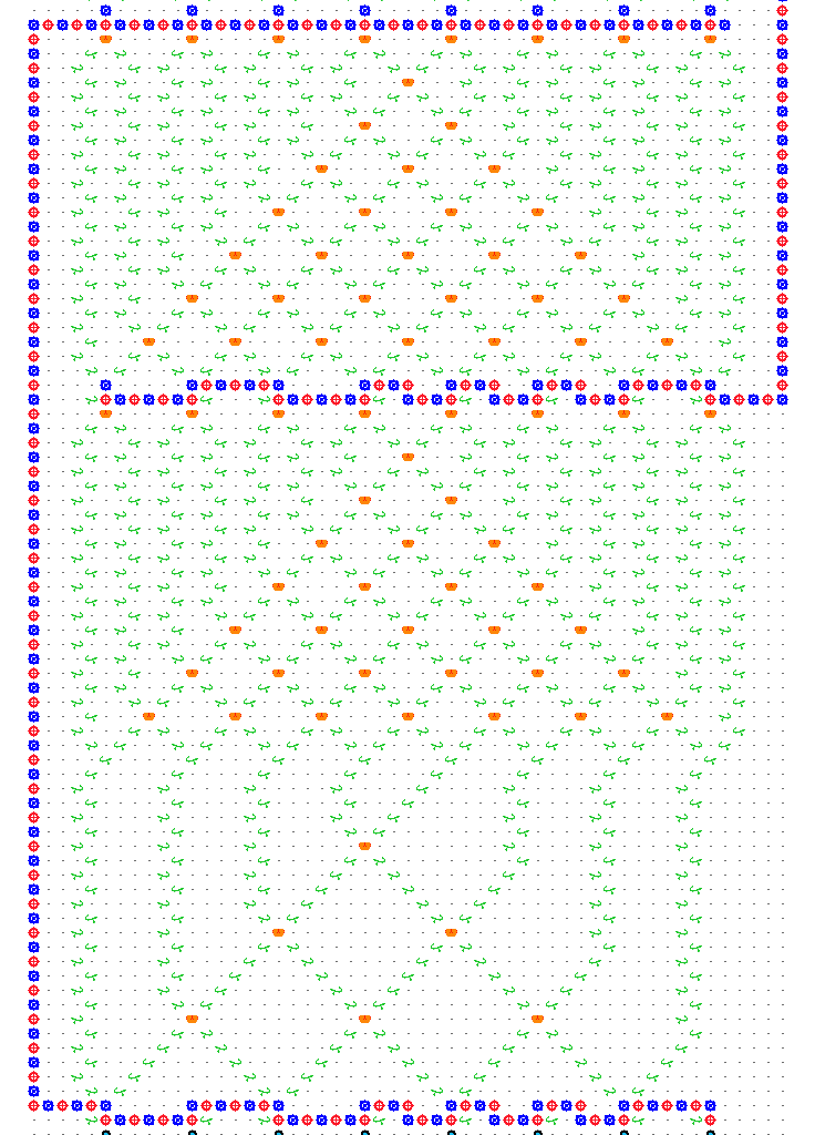
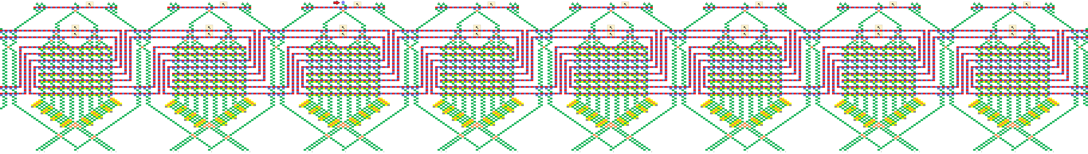
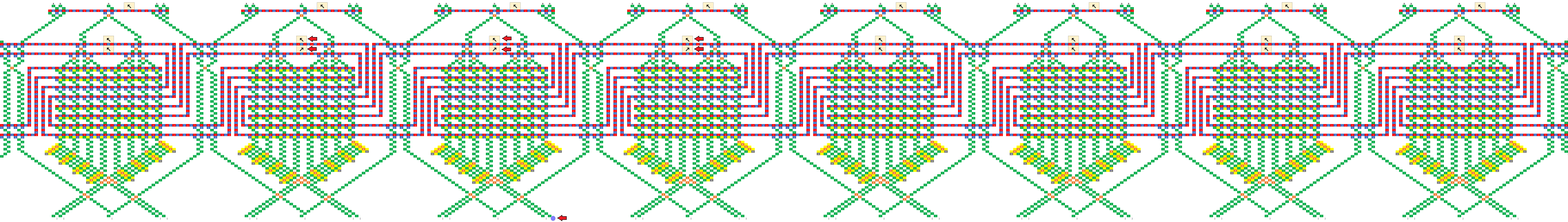
Great questions! Yeah, I was writing it all up near midnight, so probably was not as clear as I’d have liked to be. The number of bits in the string would be fixed, however the schematic at the end of my post suggests it’s possible to treat the two ends as neighbors, forming a topological loop, which takes care of edge effects. It would also be possible to treat the end neighbors as zeros, by always routing the ball at the top into the 000 column, and by having a fixed routing that pushes 0 onto the stack before the last write stripe.
-
Yes that’s exactly right, and the output would be read out in the same way.
-
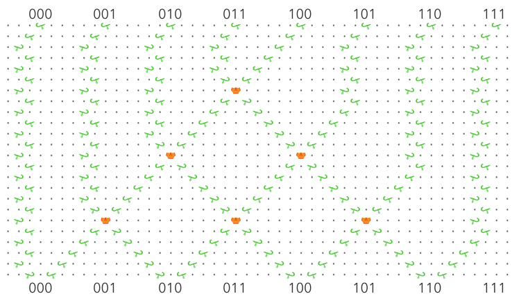
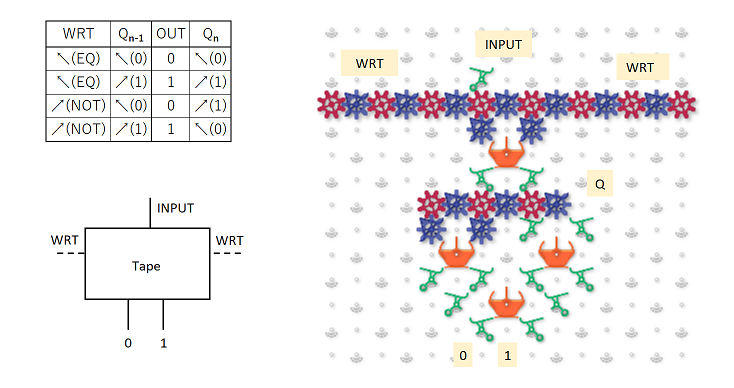
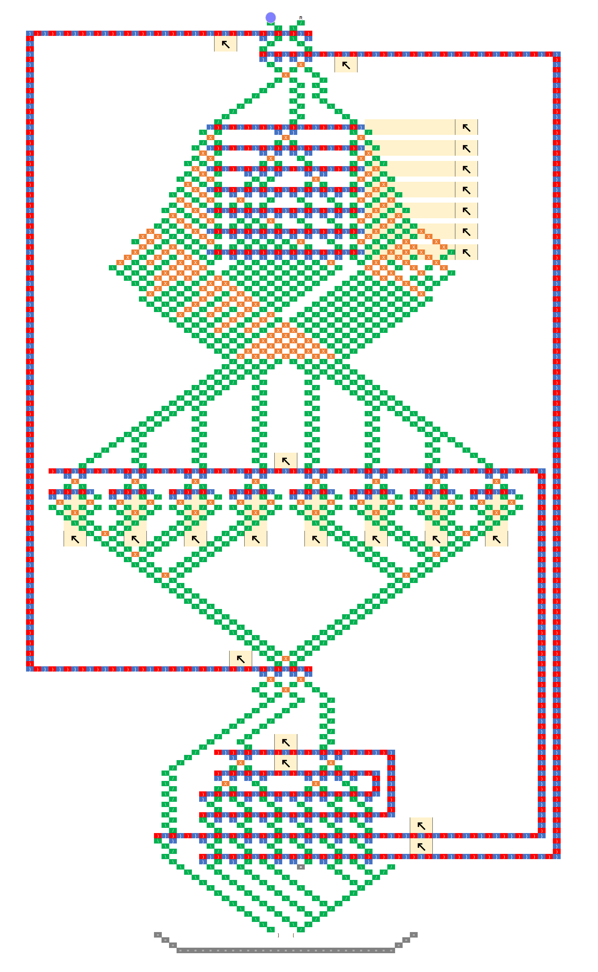
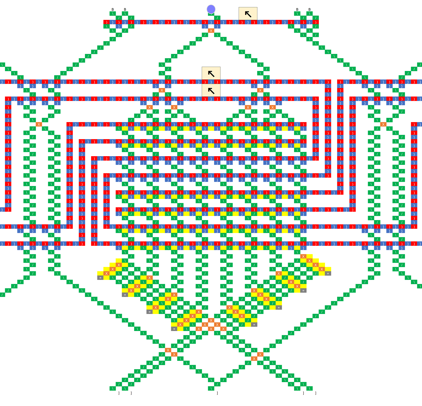
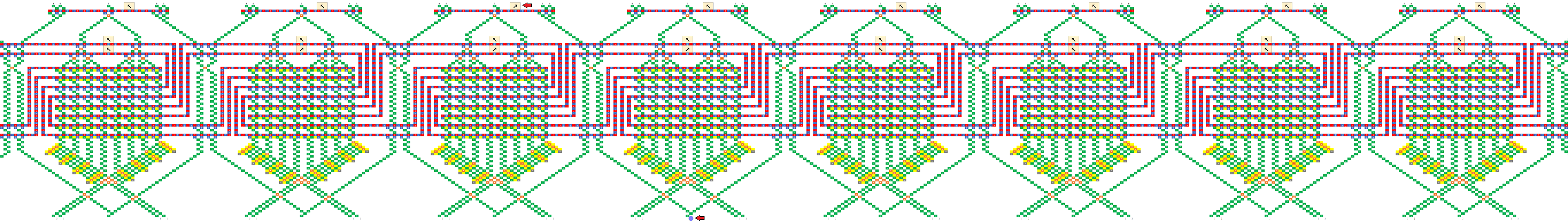
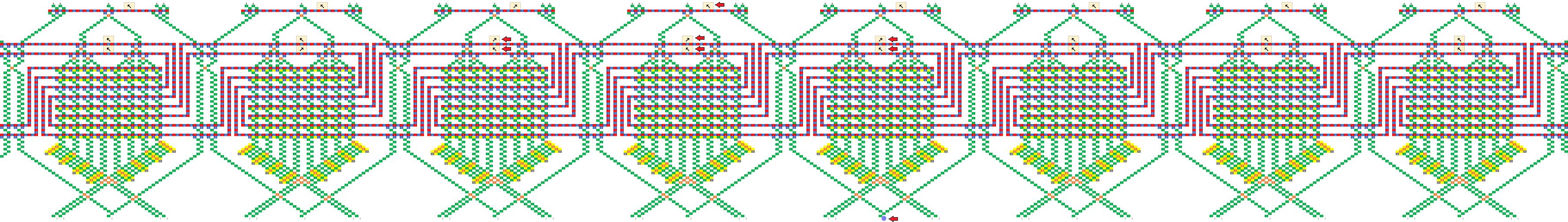
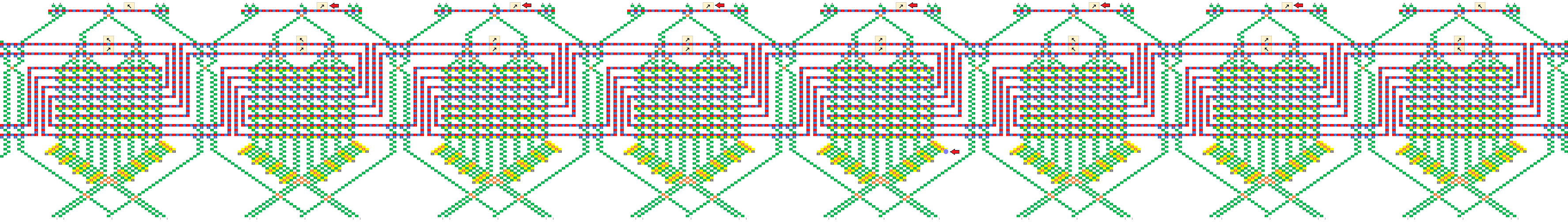
It actually doesn’t matter what column the ball drops into, assuming we use the loop topology like the schematic at the bottom, and assuming the bit-shifting sub-unit works as intended. If you look at the black-and-white schematic at the end, the ball falls through three “read stripes” before it hits the first write stripe, so three bits have been pushed onto a three bit register and all information about the initial column has been lost. An essential part of the design is to throw away one bit of information each time the ball goes through a stripe.
-
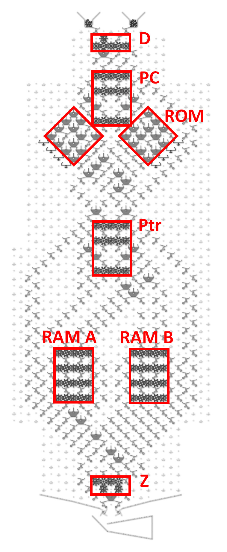
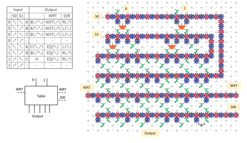
I think the confusing thing here is that when we’re about to apply the rule to a bit, call it C, that bit was actually pushed onto the stack two levels above, so the order of the bits we’re evaluating would be CBD instead of the usual BCD. You might be able to intuit this just from the shape of the C units, because the top of each C is always three steps above the bottom, and the center of the C includes one bit from above and one from below. Regardless of the order the bits are in, we can encode any rule as long as that order is consistent. Not really sure if that clears anything up, but just imagine pushing a bit into the register every time the ball passes through a stripe, whether it’s reading or writing.
-
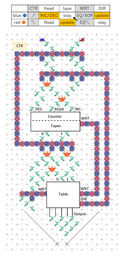
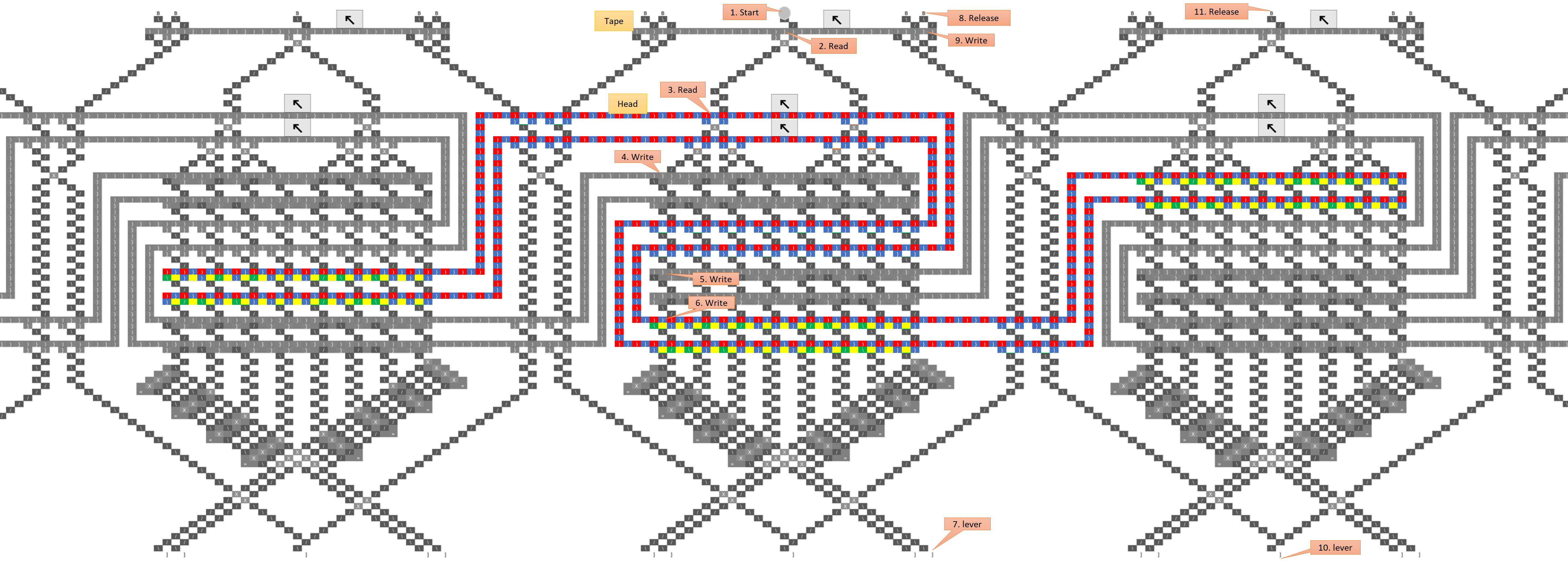
No, the “destructive write” sub-unit writes a 1 or a zero, but always reads the bit’s prior value. So just as bit 3 is about to be shifted off the left end of the stack, its current value is shifted back onto the right end so it can act as a neighbor for bit 4. After that, the ball can never pass through bit 3 again until the next generation, so the new value won’t affect the result. Maybe a good way to explain the evaluation order is to write out the string of bits being pushed onto the register, and then pull out all the groupings that are evaluated as neighborhoods. So following the black-and-white schematic above, the bit stream going into the register looks like this:
READ: 071021324354657607
........v.v.v.v.v.v.v.v.
EVAL: ..0.1.2.3.4.5.6.7.
Which breaks the bits into the following groups:
- 071 => 0
- 102 => 1
- 213 => 2
- 324 => 3
- 435 => 4
- 546 => 5
- 657 => 6
- 760 => 7
As you can see, each cell has its neighborhood in the register when the rule is evaluated, only the positions of the current cell and its left-hand neighbor are swapped.
- If you look at the bitstream breakdown above, you can see that three bits have been pushed by the time the first bit needs to be evaluated, so the initial position of the ball should have been lost and it doesn’t matter where we drop it in. However, as a side note I was thinking that a general-purpose computer would be much easier to implement if we could have any number of ball-drop/lever combos (i.e. considering that unit like any other part). If we had that, we could preserve the ball’s position between runs and use it to pass potentially quite a lot of information from the bottom of the board to the top without worrying about crossing gear trains. I’d expand on that idea but it’s off-topic for the moment. Although dang, I just started to wonder what really stops us from warping the board into a giant cylinder (in our imaginations of course), and rotating it as the ball drops such that the ball is always seeing the proper slope? It hardly seems like the board being planar is an essential requirement of the TT “platform”. Heck if you really want to bend your brain, imagine the TT as a mobius strip…
Anyway I hope that helps a little? I’m strongly considering investing some time in writing a simulator that can handle boards of arbitrary size, because part of the difficulty here is that we have to execute these kind of designs in our heads and it does start to bend the brain. Several times in writing the above post, I was sure I’d screwed something up, and I definitely am not ruling that out until I can see a CA rule running correctly on simulated hardware.
EDIT
Just noticed that I replied to the thread instead of to you @lennypitt, so tagging you now.
Also, I just remembered a question asked elsewhere on the forum about how to translate the insights gained from the TT into insights about the computers we’re familiar with. I think the missing link could be filled by software. Working with the board builds our intuition about the components, then we can carry that into a software simulation and continue to build larger and larger machines there, just as @elendiastarman and co did with WireWorld and GoL. This process could truly bridge the gap to “real” computers. So @paul, are there any plans for a software extension? I have the ambition and capability to do something really pretty and powerful, but we’ll have to see if I can actually commit the time. Regardless, I’d be into joining in on a group effort if such is being organized, or laying the foundation layer if not.